Model Service Access from Application Software Using Scoped Simulink Functions
This example shows how to model services and accessing these services from a separate component.
In this example, a simple, randomized motion detection service is defined and accessed by the client motion detection application software. The service has two functions defined, read and write. The client calls the read and write functions to record when motion is detected. This client and server interaction is modeled using scoped Simulink® functions and a Stateflow® chart.

Implement Simulink Function and Function Callers
Open the model.
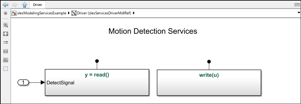
open_system('ServiceAccessSoftwareExample');The motion detection services model, MotionDetectionServices.slx, is the server model that defines the functions. The model has one input of a random number between 0 and 1, which is generated by the Random Number block. This random number is the output argument y of the read function implemented in the read Simulink Function block. The write function, implemented in the write Simulink Function block, copies input argument u. The read and write functions record when motion is detected.

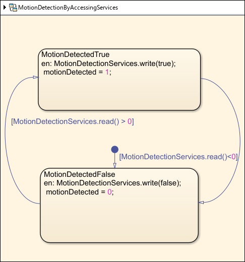
You can use a Stateflow chart to send data through an input argument to a Simulink Function block. In this example, the read and write functions are called from the MotionDetectionByAccessingServices chart in the client model, MotionDetectionSoftware.slx. In the chart, to identify the function to be called, the function call uses the model file name as the scope name followed by the function name. For example, the software calls the write function using the following notation: MotionDetectionServices.write(true).
In the services model, you can see that the write function has an input argument u. The input argument is inherited from the services model, which allows the software model to be compiled independently from the services model.

Simulate Services and Display Function Sequences
Run the model.
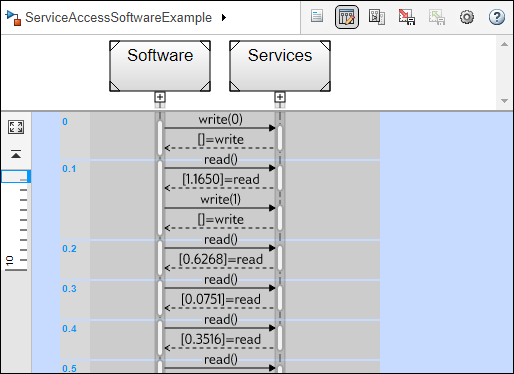
sim('ServiceAccessSoftwareExample');To view the sequence of function calls throughout the simulation of the model, open the Sequence Viewer by double-clicking on the Sequence Viewer block in the model. You can also open the tool from the Simulink Toolstrip: under the Simulation tab, in the Review Results section, click Sequence Viewer.
The Sequence Viewer window represents each block in the model as a vertical lifeline with simulation time progressing downward. This information allows you to understand the flow of calls with respect to time and analyze the arguments sent during these calls to functions.
In this example, you can see when the Software component calls the read and write functions. Function calls are displayed as solid arrows labeled with the format function_name(argument_list). You can see the Services component reply to the function calls from the Software component. Replies to function calls are displayed as dashed arrows labeled with the format [argument_list]=function_name.

See Also
Simulink Function | Random Number | Chart (Stateflow) | Sequence Viewer