服务接口概述
当您的应用程序或软件组件需要通过功能接口相互通信时,请使用面向服务的通信,由不同组件根据目标平台提供和请求服务。您可以使用面向服务的架构来决定在部署后在组件中实现函数。面向服务的架构使您可以将组件视为微服务,这些微服务可实现强大的功能,例如无线更新和云功能。System Composer™ 允许您使用服务接口对这些场景进行建模。
您可以使用 System Composer 中的软件架构在架构级别对面向服务的通信进行建模。从架构级别开始,您可以设计服务接口和组件,而无需考虑其行为的实现。架构中的端口和接口描述了系统应该“做什么”,而链接的 Simulink® 模型中的行为实现描述了组件应该“如何”做。
从架构级别开始,您可以使用以下方法为组件定义 Simulink 行为:
使用预配置的 Simulink 模板。
System Composer 可以为您提供预配置的 Simulink 模型。
在 Simulink 中手动建模您的行为,并将模型链接到您的软件架构组件。有关详细信息,请参阅Model Client and Server Components Using Function Ports。
本主题介绍如何从 System Composer 软件架构开始,使用 Simulink 实现组件行为,对面向服务的通信进行建模。
面向服务的架构的结构
面向服务的架构由以下元素组成:
软件组件是针对软件实体(包括其接口)的组件特化。
服务器是定义并提供函数的组件。
客户端是向服务器发送请求的组件。
服务接口定义客户端和服务器组件之间的功能接口。每个服务接口由一个或多个函数元素组成。
一个服务是一个功能单元。
函数元素描述客户端-服务器接口中函数的属性。
客户端和服务器通常用于在分布式系统中分配功能或访问云 API 提供服务。因此,调用服务可能需要资源,您可能需要指定执行是同步还是异步。
同步执行是指客户端向服务器发送请求后,函数立即运行,并将输出参量返回给客户端。
异步执行是指客户端向服务器发送请求后,函数根据优先级顺序异步执行,并返回输出参量给客户端。
使用 System Composer 编写服务接口
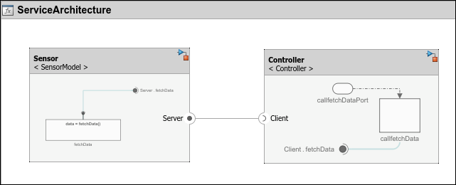
在 System Composer 中,要连接客户端和服务器组件,请使用客户端和服务器端口。

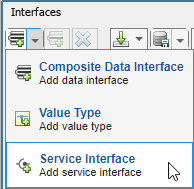
连接客户端和服务器组件后,您可以通过创建服务接口来指定函数元素。要创建服务接口,请打开接口编辑器,点击向下箭头,然后选择服务接口。
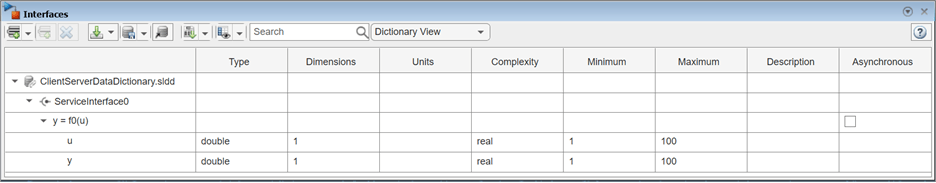
您可以在软件架构中使用接口编辑器创建函数。对于服务接口中的每个函数,添加一个函数元素。通过选择异步参数来指定函数是否为异步函数。要定义函数的名称和参数,请编辑函数原型。函数原型下方是函数的参数,以函数参量表示。对于每个函数参量,您可以在 Type、Dimensions、Units、Complexity 和 Asynchronous 列中指定值。
定义并选择服务接口后,您可以通过右键点击端口并选择应用选定接口.
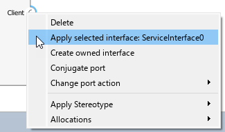
,将该接口分配给架构中的客户端和服务器端口。
使用序列图描述客户端与服务器之间的交互
自 R2024b 起
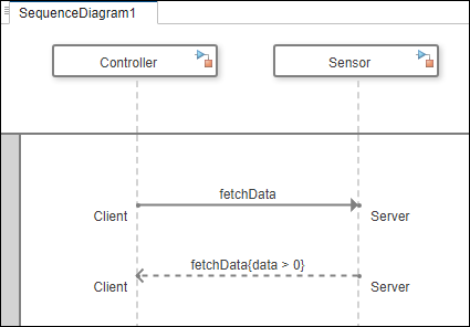
您可以使用 System Composer 中的序列图来描述客户端和服务器组件之间的交互。在设计面向服务的架构时,使用序列图来表示组件交互,这些交互由一系列调用和响应消息组成。在序列图中,客户端组件通过 call message 将请求发送到服务器组件。作为交换,服务器组件将 response message 返回给客户端组件。
有关序列图概念的更多信息,请参阅使用序列图描述系统行为。
编写客户端与服务器组件之间的调用和响应消息
创建一个序列图,根据您在接口编辑器中指定的服务接口、函数和函数参量,指定组件之间的预期交互。
在 System Composer 工具栏的建模选项卡中的图部分,点击序列图。
在架构视图库中,选择 新建 > 序列图。
从模型浏览器中将架构组件拖到画布上,以创建生命线。
从一条生命线到另一条生命线画一条线,以创建消息。
要从客户端向服务器发送一个 call message,请点击 Create a call message from client port to server port
 按钮。在 To 字段中,选择或键入服务器端口名称,在 From 字段中,选择或键入客户端端口名称。调用消息由实线和实箭头表示。
要从服务器向客户端发送一个 response message,请点击 Create a response message from server port to client port
 按钮。在 To 字段中,选择或键入客户端端口名称,在 From 字段中,选择或键入服务器端口名称。响应消息由带线箭头的虚线表示。
使用消息标签描述组件交互。消息标签有一个触发器、一个可选的保护器和一个可选的约束,形式为
trigger[guard]{constraint}。在调用和响应消息中:trigger指定函数的名称,分别表示客户端请求的到达(调用消息)和服务器响应的返回(响应消息)。guard是一个布尔表达式,用于确定消息是否发生。仅当检测到有效的触发条件时,才会对保护条件进行计算。constraint是一个布尔表达式,包括源组件的输入信号和函数参量。
调用消息的保护和约束表达式可以包括函数的输入参量和客户端组件的任何输入信号。同样,响应消息中的保护和约束表达式可以包括函数的输入和输出参量以及服务器组件的任何输入信号。
使用 Simulink 实现函数的行为
要实现函数的行为,可以创建 Simulink 行为模型。
定义并实现以下行为:
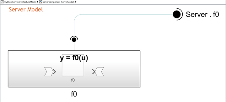
您的服务器组件,使用 Simulink 导出函数模型。有关导出函数模型的更多信息,请参阅导出函数模型概述。
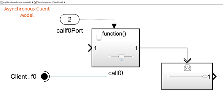
客户端组件使用基于速率的 Simulink 模型或导出函数模型。
注意
在调用同步服务时,支持基于速率的行为模型。 (自 R2024b 起)
在实现对异步服务的调用时,必须使用导出函数行为模型。
要创建 Simulink 行为,请右键点击组件,选择创建 Simulink 行为,并将 Simulink 行为的类型设置为模型引用: 基于速率或模型引用: 导出函数。
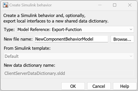
创建的模型是一个模板模型,其中包含在 System Composer 中创建的服务接口。在软件架构中,您将模型视为组件中的模型引用。该行为的实现取决于函数执行的同步性。
您可以在服务器模型中通过在 Simulink Function 模块中实现所需的服务算法来定义服务。将任何必要的模块添加到 Simulink Function 模块中,并确保这些模块与参量模块相连。ArgIn 和 ArgOut 模块分别代表函数的输入和输出参量。
您可以在客户端模型中通过在 Function-Call Subsystem 模块中实现函数调用来调用您的服务。将任何必要的模块添加到函数调用子系统中,以表示任何输入和输出。对于异步执行,输出消息是一个消息负载。
有关实现函数行为的更多信息,请参阅Model Client and Server Components Using Function Ports。
使用 System Composer 仿真您的服务
您可以通过编译和运行面向服务的架构模型来仿真面向服务的通信。
要运行架构模型,请点击运行按钮或使用 sim 函数。例如,如果您的模型名为 myServiceModel,请输入以下命令运行模型:
sim('myServiceModel')仿真完成后,您可以使用仿真数据检查器和序列查看器工具分析和可视化信号。
您可以从函数编辑器中修改服务接口中函数的执行顺序。
有关详细信息,请参阅传感器之间面向服务的通信建模。
使用 Simulink Test 测试您的服务接口
自 R2024a 起
要测试服务接口,您可以为具有客户端和服务器端口的架构和组件创建测试框架。创建测试框架需要获得 Simulink Test™ 许可。测试框架是一个模型,允许您在与原始模型分离的环境中测试模型或模型组件。
创建测试框架时,Simulink Test 会生成一个测试框架模型和一个模拟架构模型。
测试框架模型提供了一个模型,通过在调度器模块中指定输入和输出以及测试用例来配置测试场景。
模拟架构模型包含用于实现与被测组件通信的客户端或服务器组件的模拟组件。
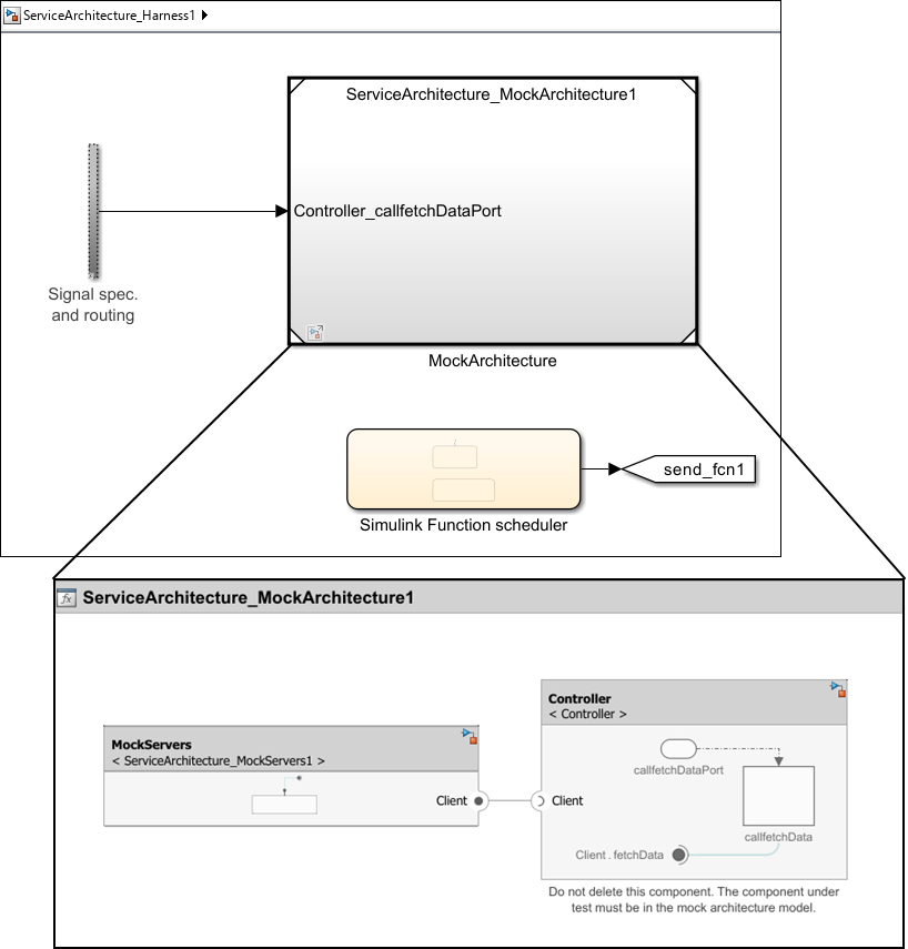
在此示例中,为具有客户端端口的组件 Controller 创建了一个测试框架。
ServiceArchitecture_Harness1是测试框架模型。ServiceArchitecture_MockArchitecture1是模拟架构模型。ServiceArchitecture_MockServers1是连接到被测组件客户端端口的附加模拟组件,用于仿真服务接口。
要创建测试框架,请在架构或组件中右键点击,点击测试框架,然后选择创建。或者,使用 sltest.harness.create (Simulink Test) 函数。
有关示例,请参阅传感器之间面向服务的通信建模。
使用 Embedded Coder 生成代码
生成代码需要 Embedded Coder® 许可证。
您可以从软件架构模型为每个组件生成代码。生成的代码包含组件每个函数的入口点。要生成代码,从 App 选项卡中选择 Embedded Coder。在生成代码选项卡中,选择生成代码。
另请参阅
模块
- Function Element | Function Element Call | Simulink Function | Function Caller | Function-Call Subsystem | Message Triggered Subsystem | Reference Component