传感器之间面向服务的通信建模
此示例展示了如何从 System Composer™ 软件架构开始,使用 Simulink® 实现组件行为,从而对面向服务的通信进行建模。从架构层面建模面向服务的通信,您可以设计服务接口和组件,而无需考虑其功能的实现。有关详细信息,请参阅服务接口概述。
在此示例中,模型 slexServiceInterfaceExample 由一个控制器组件 Controller 和两个传感器组件 Sensor1 和 Sensor2 组成。将两个传感器组件建模为同一引用模型 scSensorModelRef 的两个不同实例。两个引用的传感器模型都输出不同幅度的正弦波。引用模型定义了两个服务:reset,用于重置传感器随时间漂移的值;fetchData,用于读取最新的传感器值。您在控制器和两个传感器实例之间指定一个服务接口,这样控制器就可以调用 reset 或 fetchData 来访问引用传感器组件的特定实例。
打开模型。
model = systemcomposer.openModel('scServiceInterfaceExample.slx');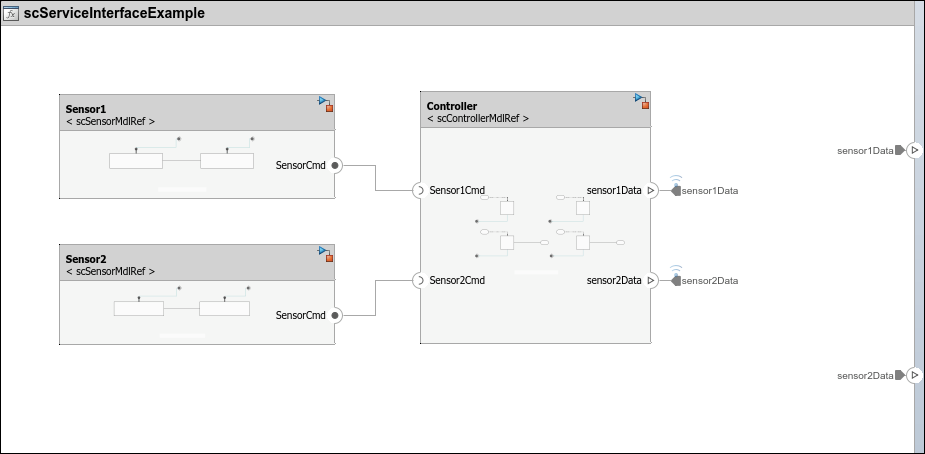
通过客户端和服务器端口进行组件与组件交互
控制器组件使用服务器端口和客户端端口与传感器组件进行交互。球形和插座图标分别代表服务器和客户端端口。
定义服务接口
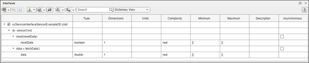
服务接口定义客户端和服务器组件之间的功能接口。您可以通过接口编辑器定义服务接口 sensorCmd。要访问接口编辑器,请转到建模选项卡,在设计部分中,选择接口编辑器。服务接口 sensorCmd 在所有引用的模型中使用,并存储在数据字典 slexServiceInterfaceExample.sldd 中。
sensorCmd 服务接口包含两个函数元素:reset 和 fetchData。在接口编辑器中,您可以指定函数原型来定义输入和输出参量。函数 reset 的函数原型为 reset(resetData),它指定了一个输入函数参量 resetData。函数 fetchData 的函数原型为 data = fetchData(),它指定了一个输出函数参量 data。对于每个函数参量,您可以在 Type、 Dimensions、 Units、Complexity、Minimum、Maximum 和 Description 列中指定一个值。
在 Simulink 中实现函数行为
服务接口中指定的函数的行为在引用的模型中定义。在面向服务的架构中,您可以在基于速率或导出函数的模型中实现这些函数行为模型。
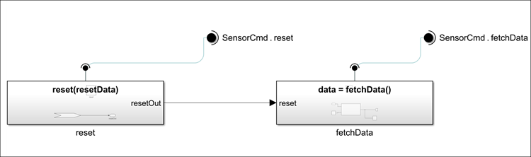
服务器组件模型
scSensorMdlRef 模型是一个导出函数模型,代表传感器的行为。在 scSensorMdlRef 中,您在相应的 Simulink 函数模块中定义了两个函数 reset 和 fetchData。函数 reset 有一个布尔输入参量 resetData。默认情况下,resetData 为假,因此,在控制器将 reset 设置为 resetData 之前,true 函数不会重置传感器。
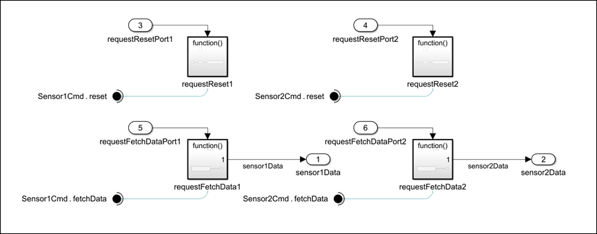
客户端组件模型
scControllerMdlRef 模型是一个基于导出的模型,代表控制器的行为。在 scControllerMdlRef 中,每个传感器都有一个 requestReset 和 requestFetchData 函数调用子系统。
有关服务器和客户端模型的结构和功能的详细信息,请参阅Model Client and Server Components Using Function Ports。
调度函数和仿真
要运行模型,请使用函数 sim。
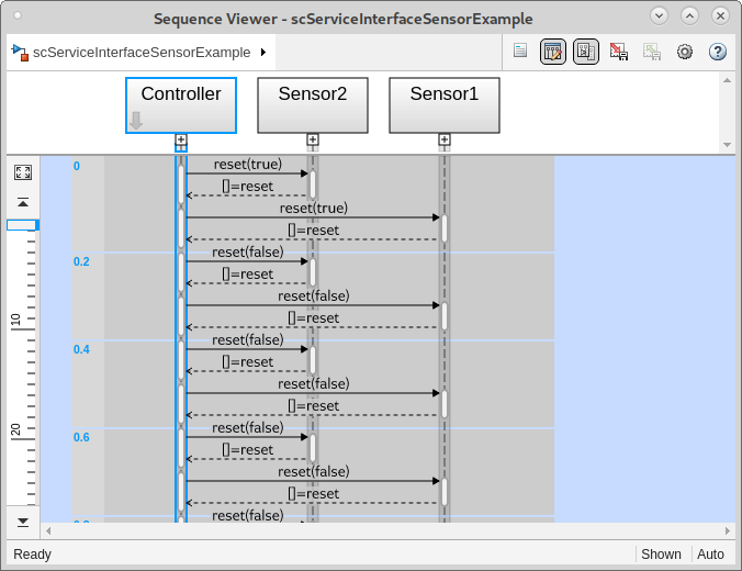
sim('scServiceInterfaceExample');要查看模型仿真过程中函数调用的顺序,请打开“序列查看器”。
转到仿真选项卡,在查看结果部分中,选择序列查看器。
Controller 组件的测试服务接口
创建测试框架需要获得 Simulink® Test™ 许可。要为 Controller 组件创建测试框架,右键点击 Controller 组件,点击 Test Harness,然后选择为 'Controller' 创建。在创建测试框架对话框中,点击确定。
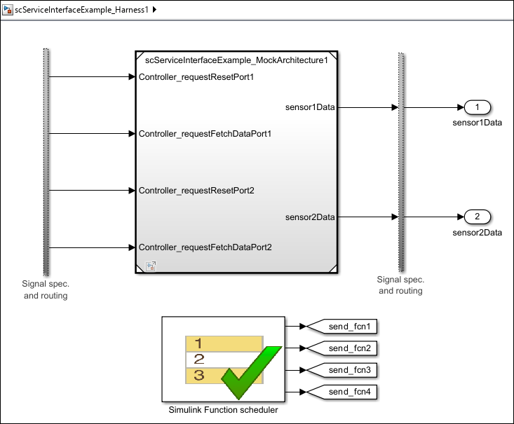
当您创建测试框架时,Simulink Test 会生成一个测试框架模型和一个模拟架构模型。
测试框架模型
scServiceInterfaceExample_HarnessN提供了一个模型,用于在 Simulink 函数调度器模块中配置测试场景。模拟架构模型
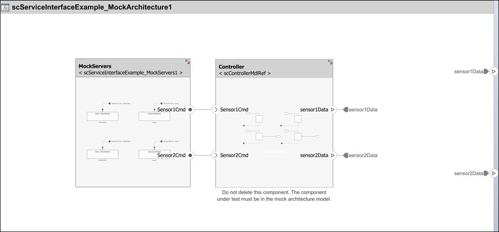
scServiceInterfaceExample_MockArchitecture1包含模拟组件scServiceInterfaceExample_MockServers1,用于实现与被测组件Controller通信的服务。
要打开模拟架构模型,请双击测试框架模型中的 scServiceInterfaceExample_MockArchitecture1 模块。
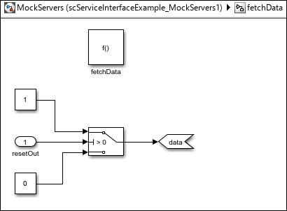
实现模拟组件的行为
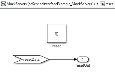
双击 MockServers 架构模型中的 scServiceInterfaceExample_MockArchitecture1 组件,打开模拟服务器模型。
控制器调用 reset 函数和 fetchData 函数。为了使模拟服务器组件的测试输出符合预期,您必须向模拟服务器提供测试输入和输出。
reset Function
要实现函数 reset 的模拟行为,可以添加一个 Outport 模块来记录 resetData 的值。
fetchData 函数
要实现函数 fetchData 的模拟行为,可以添加一个 Switch 模块来控制该函数的输出。您可以将 resetData 端口连接到控制输入信号,并添加两个 Constant 模块用于数据输入信号。
仿真测试框架
在测试框架模型中,有两个 Outport 模块,它们记录 Sensor1 和 Sensor2 的信号。
要仿真测试,必须添加一个步骤转移。打开测试框架模型中的 Test Sequence (Simulink Test) 模块,在 Run 步骤的转移列中,添加 true 作为进入下一步的条件。
点击仿真选项卡中的运行,以仿真框架。
打开 仿真数据检查器 以观察
Sensor1和Sensor2组件的记录输出。
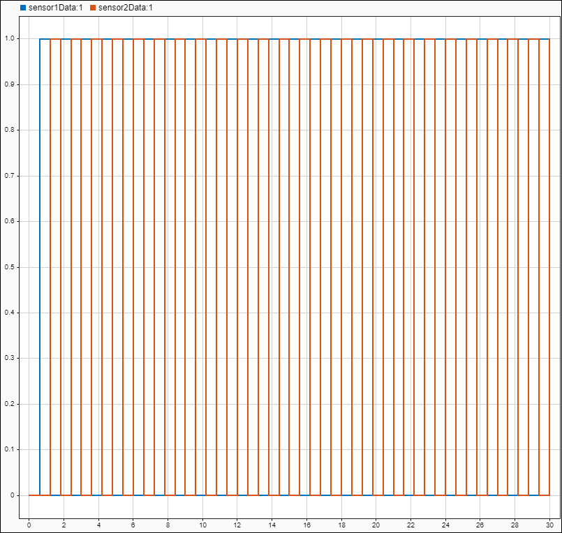
在此示例中,被测组件为 Controller,因此在仿真数据检查器中,您可以观察来自传感器的信号,以确保 Controller 能够按照预期调用 reset 和 fetchData 函数。
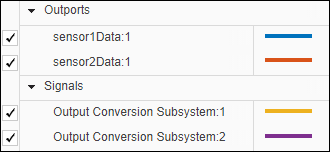
在检查选项卡中,选择并取消选择
sensor1Data:1和Output Conversion Subsystem:1信号,以观察信号是否匹配。同样地,选择并取消选择
sensor2Data和Output Conversion Subsystem:2信号,以观察这些信号是否匹配。
如果传感器和客户端组件之间的信号匹配,则测试完成。有关测试服务接口的更多信息,请参阅使用 Simulink Test 测试您的服务接口。
生成代码
生成代码需要 Embedded Coder® 许可证。
要生成包含服务接口 sensorCmd 的模型代码,请使用以下命令。
slbuild('scServiceInterfaceExample');
生成的代码包括服务接口 sensorCmd 作为抽象类,从而使实现与接口分离。此外,组件的每个函数都有一个入口点。
另请参阅
Function Element | Function Element Call | Simulink Function | Function Caller | Function-Call Subsystem | addServiceInterface | setFunctionPrototype | getFunctionArgument