Software Component Designer
R2026bDesign, simulate, and deploy software components for service-oriented architecture (SOA) applications
Since R2026b
Description
The Software Component Designer app provides tools to configure a model as a software component model, define data and service interfaces on ports, and specify communication and execution behavior using quality of service (QoS) properties.
Note
This app requires the Software Component Designer for Simulink® support package.
When you design software for service-oriented architecture applications, define how components communicate and execute at run time independently of the algorithms they implement. The Software Component Designer app lets you capture these design decisions early, so that the app preserves communication and execution behavior from simulation through code generation and deployment.
Use the app to:
Define data and service interfaces on component ports to establish clear contracts between components
Specify QoS properties, such as
QueuedorLatestValuereceiver services and periodic or data-triggered execution, to define communication and execution behaviorIntegrate components into software architecture models and simulate them with a mock run-time environment (RTE) to verify system-level behavior before deployment
Integrate components into architecture test harnesses to test software components and compositions with QoS properties
If you have the Embedded Coder® Support Package for Service-Oriented Applications on Linux®, you can also generate component code, build deployable applications, and deploy them to Linux platforms.
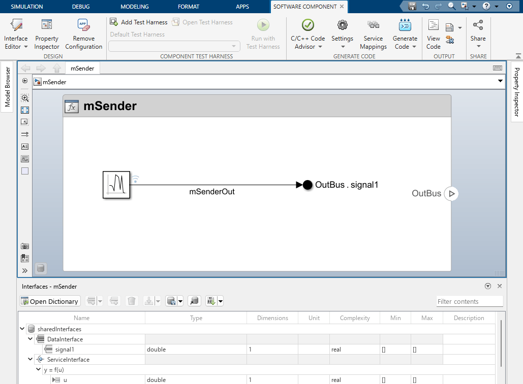
Open the Software Component Designer App
Simulink Toolstrip: On the Apps tab, under Code Generation, click Software Component Designer
 .
.System Composer™ Toolstrip: On the Apps tab, under Code Generation, click Software Component Designer.
Examples
- Model and Simulate Services of Brake Control System
- Create Software Component Models in Simulink
- Configure Communication and Execution Behavior of Software Components
- Validate Component Behaviors Using Architecture Test Harnesses (System Composer)
- Integrate Software Components into Compositions Using Software Component Designer (System Composer)
- Simulate Software Architectures to Validate Run-time Behavior (System Composer)
Parameters
Tips
When you first open the app on a model, the app configures the model as a software component. To learn about the configuration the app applies and how to begin designing components, see Create Software Component Models in Simulink.
Save interfaces in Simulink data dictionaries (
.sldd) to share them across multiple software component models.The app supports two communication patterns: send-receive for data exchange and client-server for request-response operations. For more information, see Configure Communication and Execution Behavior of Software Components.
Version History
Introduced in R2026b

