Set Position of Bebop Drone on Gazebo Simulator from Android Device Using ROS
This example shows how to generate an Android® application to set the position of the Parrot® Bebop drone on the Gazebo simulator using Simulink® Support Package for Android Devices. In this example, your computer is configured as ROS master, and the Android device is configured as ROS client. The device connects to the computer through the Robot Operating System (ROS) interface. The data received from the device is displayed using the simulator running on the computer.
Requirements
Hardware Requirements
Android device
USB cable
Software Requirements
Install these products on your computer:
MATLAB® (R2018a or later)
Simulink (R2018a or later)
A MathWorks®-provided Virtual Machine (VM)
Prerequisites
Configure the Android device by using
androidhwsetup.Complete the Getting Started with Android Devices example.
Introduction
ROS is a communication interface that enables different parts of a robot system to discover, send, and receive data. Using the ToApp block from the Simulink Support Package for Android Devices, you can exchange data with ROS-enabled physical robots or robot simulators such as Gazebo. For more information, see the Concepts section on the ROS website.
Step 1: Run the Gazebo Simulator on the Computer
1. Install the MathWorks-provided VM on your computer. If you have already installed this VM or if you choose to use your own VM, skip this step.
2. Open a new terminal on the VM installed on your computer.
3. In the terminal window, type ifconfig. This command displays the configuration of the network interfaces of the VM. Under eth0, the inet address displays the IP address of the VM. Note the IP address for later use.
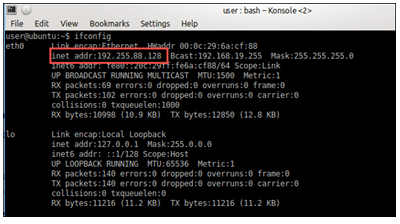
4. Set the values of the standard ROS environment variables, ROS_MASTER_URI and ROS_HOSTNAME, by executing these commands in the terminal. Replace IP_OF_VM with the IP address of the VM noted in the previous step.
echo export ROS_MASTER_URI=http://IP_OF_VM:11311 >> ~/.bashrc
echo export ROS_HOSTNAME=IP_OF_VM >> ~/.bashrc
5. Perform these steps to run the installRotorS.sh file. The installRotorS.sh file contains a script to download all the packages required to launch the Gazebo simulator and to run the Bebop drone on the simulator.
a. Change the MATLAB Current Folder by using this command in the MATLAB Command Window:
cd(fullfile(matlabshared.supportpkg.getSupportPackageRoot,'toolbox','target','supportpackages','android','androidexamples','ROSonAndroid'))
b. Copy the installRotorS.sh file to the /home/user path of the VM.
c. In the terminal window, execute these commands:
chmod a+x installRotorS.sh
./installRotorS.sh
d. Close the terminal and reopen it.
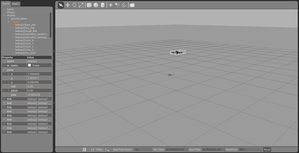
6. Launch the Gazebo simulator by executing this command. You will see a Bebop drone in the render window of the simulator.
roslaunch rotors_gazebo bebop_hover.launch
Step 2: Generate an Android Project Using Simulink
This section explains how to generate an Android project from a Simulink model.
Open the Simulink Model
1. Connect the Android device to your computer with a USB cable.
2. Install the Simulink Support Package for Android Devices. If you have already installed the support package, skip this step.
3. Open the ControlDronePosition Simulink model. This model is preconfigured to run on the Android device.
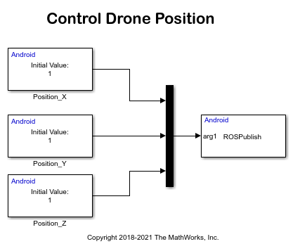
The model has these blocks:
Data Input: Using the Position_X, Position_Y, and Position_Z blocks, you can change the x-, y-, and z- coordinates of the Bebop drone on the simulator.
ToApp: The block accepts the position data of the drone and sends the data to the
ROS Publishmethod. TheROS Publishmethod publishes the data to the computer.
Configure the Simulink Model
1. In the Simulink editor, select Simulation > Model Configuration Parameters.
2. In the Configuration Parameters dialog box, select Hardware Implementation.
3. Set the Hardware board parameter to Android Device. This selection automatically populates the parameters in the Hardware board settings with the default values for Android.
a. From the Groups list under Target hardware resources, select Device options.
b. From the Device list, select your Android device. If your device is not listed, click Refresh.
Note: If your device is not listed even after clicking the Refresh button, ensure that you have enabled the USB debugging option on your device. To enable USB debugging, enter androidhwsetup in the MATLAB Command Window and follow the onscreen instructions.
4. Click Apply. Click OK to close the dialog box.
Deploy Simulink Model on Android Device
On the Hardware tab of the Simulink model, in the Mode section, select Run on board and then click Build, Deploy & Start. The lower-left corner of the model window displays status while Simulink builds the model on the computer. After successfully building the model, a project file is generated in the MATLAB build folder at MATLAB_build_folder/modelName_ert_rtw/modelName. For example, L:/workspace/ControlDrone/ControlDronePosition_ert_rtw/ControlDronePosition.
Step 3: Import the Project and Add ROS Dependencies in Android Studio
1. Import the generated project to Android Studio by following the steps as described in Import Project to Google Android Studio.
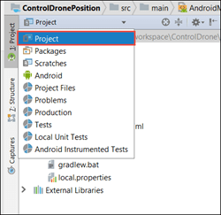
2. In Android Studio, select the Project option from the top-left drop-down menu above the File Explorer.
3. Open the build.gradle file of your project and update the file by adding code at the positions labeled in the image.
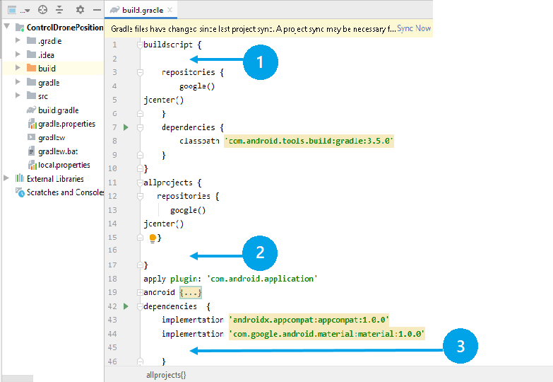
Position 1 — Add this line in the buildscript section.
apply from: "https://github.com/rosjava/android_core/raw/kinetic/buildscript.gradle"
Position 2 — Add these lines in the allprojects section.
apply plugin: 'ros-android'
afterEvaluate { project -> android {// Exclude a few files that are duplicated across our dependencies and prevent packaging Android applications.
packagingOptions {exclude "META-INF/LICENSE.txt"
exclude "META-INF/NOTICE.txt"
}
}
}
Position 3 — Add these ROS dependencies below the listed dependencies.
implementation "org.ros.rosjava_core:rosjava:[0.3.2,0.4)"
implementation "org.ros.rosjava_messages:diagnostic_msgs:[1.12,1.13)"
implementation "org.ros.rosjava_messages:sensor_msgs:[1.12,1.13)"
implementation "org.ros.rosjava_messages:geometry_msgs:[1.12,1.13)"
implementation "org.ros.rosjava_core:rosjava_geometry:0.3.6"
implementation 'org.ros.rosjava_messages:visualization_msgs:[1.12,1.13)'
implementation "org.ros.rosjava_bootstrap:message_generation:[0.3,0.4)"
implementation 'org.ros.rosjava_messages:std_msgs:0.5.11'
4. Open the AndroidManifest.xml file located in the src > main folder of your project. Update the file by changing the code at the positions labeled in the image.

Position 1 — Add this code after the application tag.
xmlns:tools="http://schemas.android.com/tools"
tools:replace="android:icon"
Position 2 — Replace the action and category sections.
<action android:name="com.android.rosupport.START_MODEL_GAZEBO"/>
<category android:name="android.intent.category.DEFAULT" />
Position 3 — Add the activity and service sections immediately after the activity section.
<activity android:label="@string/app_name" android:name=".MainActivity"
android:theme="@style/MWAppTheme" android:configChanges="orientation|screenSize">
<intent-filter>
<action android:name="android.intent.action.MAIN"/>>
<category android:name="android.intent.category.LAUNCHER"/>
</intent-filter>
</activity>
<service android:name=".MWNodeMainExecutorService"
tools:ignore="ExportedService">
<intent-filter>
<action android:name="org.ros.android.NodeMainExecutorService"/>
</intent-filter>
</service>
Position 4 — Add these ROS uses-permissions below the listed uses-permission.
<uses-permission android:name="android.permission.FOREGROUND_SERVICE"/>
<uses-permission android:name="android.permission.WRITE_EXTERNAL_STORAGE"/>
<uses-permission android:name="android.permission.ACCESS_WIFI_STATE"/>
<uses-permission android:name="android.permission.CHANGE_WIFI_STATE"/>
<uses-permission android:name="android.permission.WAKE_LOCK"/>
<uses-permission android:name="android.permission.SYSTEM_ALERT_WINDOW"/>
5. Change the MATLAB Current Folder by using this command in the MATLAB Command Window:
cd(fullfile(matlabshared.supportpkg.getSupportPackageRoot,'toolbox','target','supportpackages','android','androidexamples','ROSonAndroid','ControlDronePosition'))
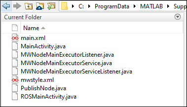
a. Copy these files and paste them in the src > main > java > com.example.ControlDronePosition folder of your project. Here, ControlDronePosition is the name of your project.
ROSMainActivity.java
PublishNode.java
MainActivity.java
MWNodeMainExecutorListener.java
MWNodeMainExecutorService.java
MWNodeMainExecutorServiceListener.java
b. Save the main.xml file in the src > main > res > layout folder of your project.
c. Save the mwstyle.xml file in the src > main > res > values folder of your project.
6. Open the ControlDronePosition.java file located in the src > main > java > com.example.ControlDronePosition folder of your project. Here, ControlDronePosition is the name of your project. Update the file by changing the code at the positions labeled in the image.
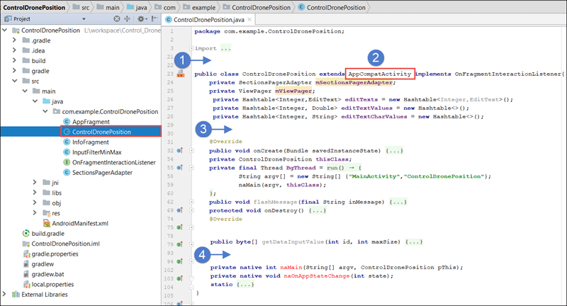
Position 1 — Add the ROS import statements.
import org.ros.node.NodeConfiguration;
import org.ros.node.NodeMainExecutor;
Position 2 — Replace AppCompactActivity with ROSMainActivity.
Position 3 — Add the PublishNode statement before the definition of the onCreate method.
PublishNode pn;
Position 4 — Add the ROSPublish and init method definitions before the definition of the naMain method.
public void ROSPublish(double[] data)
{if(pn != null)
pn.publishData(data);
}
protected void init(NodeMainExecutor nodeMainExecutor) { pn = new PublishNode("bebop2/command/pose","geometry_msgs/PoseStamped");NodeConfiguration nodeConfiguration = NodeConfiguration.newPublic(getRosHostname());
nodeConfiguration.setMasterUri(getMasterUri());
nodeMainExecutor.execute(pn, nodeConfiguration);
}
The ROSPublish method accepts the position data entered using the Data Input block of the Simulink model. The method then publishes the data to the Gazebo simulator (ROS master). The data type of the published data depends on message type of the ROS topic. In this example, the publish topic is bebop2/command/pose and the message type is geometry_msgs/PoseStamped. You can use a different topic name and message type based on the requirements of your application. The init method is called after the ROS client is created. In this function, you can specify the number of publishers and subscribers required for the application. In this example, only one publisher is required.
Step 4: Sync Project Files in Android Studio
In Android Studio, click the Sync Now button in the top-right corner of the Android Studio editor.

When syncing your project, you may see the following error message. To resolve this issue, click the link that appears in the error message.

Note: The build tools version number specified in the error message may vary depending on the version of the Android gradle plugin installed in the computer.
Step 5: Configure and Run the Android Device as ROS Client
Note: Before proceeding, ensure that your computer and the Android device are connected to the same Wi-Fi® network.
1. In the Android Studio toolbar, select Run > Run 'ControlDronePosition'. Android Studio installs the application on your device. The application starts running on the device and provides you the options to configure the device as ROS master or ROS client.
2. Select the ROS Client option to specify the IP address and the port number of the computer. In this example, the IP address is 192.255.88.128 and the port number is 11311.
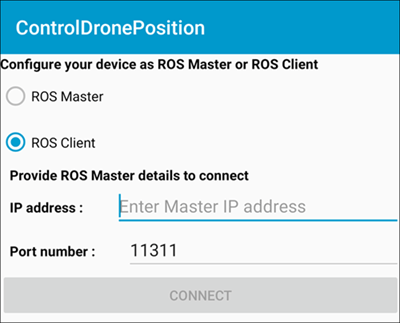
3. To connect the device to the computer, click CONNECT. The device starts sending position data specified in the Data Input block to the computer. In this example, the position specified is 1, 1, and 1. This position of the Bebop drone in the simulator changes to 1, 1, and 1.
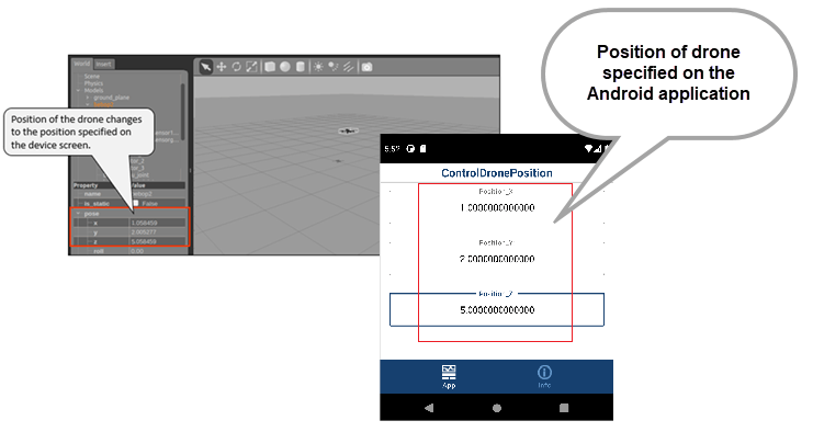
4. Change the x-, y-, and z- coordinates in the Position_X, Position_Y, and Position_Z boxes on the device screen. Observe that the position of the drone changes to the position specified in these boxes.
