Control LED Status Using BLE Peripheral and Central Devices on Arduino Boards
This example shows how to use the Simulink® Support Package for Arduino® Hardware to configure Bluetooth® Low Energy (BLE) communication between Arduino peripheral and central devices. It also shows how to control the status of an onboard LED on a peripheral device from the central device and vice versa using BLE communication.
Prerequisites
For more information on how to run a Simulink model on Arduino hardware, see Get Started with Arduino Hardware.
Required Hardware
Two Arduino boards. You can use an Arduino Nano 33 IoT, an Arduino MKR Wifi 1010, or an Arduino Nano 33 BLE Sense. For illustration purposes, this example uses one Arduino Nano 33 IoT and one Arduino Nano 33 BLE Sense.
Two breadboards.
Two pushbutton switches.
Jumper wires.
Dependencies
Implementing this example requires you to successfully deploy these Simulink models on each of the supported Arduino boards:
       Simulink Model Name    |      Deployed Hardware      |          Purpose
  -------------------------------------------------------------------------------------------
    1. arduino_BLE_peripheral |     Arduino Nano 33 IoT     | Behaves as a peripheral device
    2. arduino_BLE_central    |  Arduino Nano 33 BLE Sense  | Behaves as a central device
Hardware Setup
Connect the pushbutton switch between any GPIO pin and the ground for both the Arduino boards.
For illustration purposes, in this example, one pushbutton switch connects pin 2 and the ground of the Arduino Nano 33 IoT board while the other pushbutton connects pin 2 and the ground of the Arduino Nano 33 BLE Sense board.
Configure Arduino Peripheral Model and Calibrate Parameters
This example uses a preconfigured Simulink model from the Simulink Support Package for Arduino Hardware.
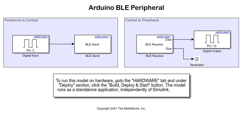
Open the arduino_BLE_peripheral Simulink model.

This Simulink model acts as a server that receives a data request from the client model and sends a response.
In peripheral mode, the services provided by the Arduino Nano 33 IoT board are made available to the Arduino Nano 33 BLE Sense board operating in central mode. After you successfully connect the Arduino peripheral and central boards, the characteristics within the service are made available. You can specify your own custom services and characteristics using your own UUIDs for the service and characteristics.
The status of the pushbutton connected to pin 2 of the Arduino peripheral device controls the LED on the Arduino central device.
On the Modeling tab of the Simulink model, select Model Settings.
In the Configuration Parameters dialog box, select Target hardware resources > BLE properties.
Configure these BLE properties.
Set Peripheral Device Name to
ArduinoBLEPeripheral.Set Peripheral Local Name to
ArduinoBLEPeripheral.
For more information on how to configure Arduino BLE properties, see BLE properties.
Peripheral to Central
The BLE Send block in the Peripheral to Central area transmits the status of the pushbutton from the Arduino board configured in peripheral mode to the Arduino board configured in central mode. This pushbutton status determines whether the LED on the central board is on or off.
Configure these parameters in the Block Parameters dialog box of the Digital Input block.
Set Pin number to
2.Set Pin mode to
Input Pullup.Set Sample time to
0.1.
Configure these parameters in the Block Parameters dialog box of the BLE Send block.
Set Mode to
Peripheral (Server).Select Specify using UUID.
Select the Service broadcasted by the BLE device. In this example, the parameter is set to
df801ed6-a405-11eb-bcbc-000000000000.Select from the available Characteristic for the service set in the Service parameter. In this example, the parameter is set to
df801ed6-a405-11eb-bcbc-000000000001.
Central to Peripheral
The BLE Receive block in the Central to Peripheral area receives the status of the pushbutton from the Arduino board configured in the central mode to the Arduino board configured in the peripheral mode. This pushbutton status determines whether the LED on the peripheral board is on or off.
Configure these parameters in the Block Parameters dialog box of the BLE Receive block.
Set Mode to
Peripheral (Server).Select Specify using UUID.
Select the Service broadcasted by the BLE device. In this example, the parameter is set to
df801ed6-a405-11eb-bcbc-000000000000.Select from the available Characteristic for the service set in the Service parameter. In this example, the parameter is set to
df801ed6-a405-11eb-bcbc-000000000002.Set Data size to
1.Set Sample time to
0.1.
Configure this parameter in the Block Parameters dialog box of the Digital Output block.
Set Pin number to
13.
Deploy Arduino Peripheral Simulink Model on Arduino Board
Connect the Arduino Nano 33 IoT board to the host computer.
Open the
arduino_BLE_peripheralSimulink model.On the Hardware tab of the Simulink model, set Hardware Board to
Arduino Nano 33 IoT.On the Hardware tab of the Simulink model, in the Mode section, select Run on board and then click Build, Deploy & Start.
Configure Arduino Central Model and Calibrate Parameters
This example uses a preconfigured Simulink model from the Simulink Support Package for Arduino Hardware.
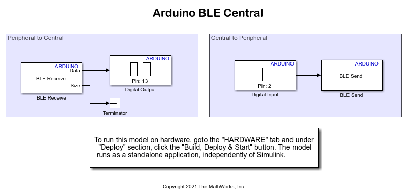
Open the arduino_BLE_central Simulink model.

This Simulink model acts as a client that sends the data requested by the server Simulink model. In the central mode, the available peripheral devices are scanned using the Hardware Setup wizard. After you select the peripheral device from the central board, the characteristics within the service are made available.
The status of the pushbutton connected to pin 2 of the Arduino central device controls the LED on the Arduino peripheral device.
Peripheral to Central
The BLE Receive block in the Peripheral to Central area receives the status of the pushbutton from the Arduino board configured in the peripheral mode to the Arduino board configured in the central mode. This pushbutton status determines whether the LED on the central board is on or off.
Configure these parameters in the Block Parameters dialog box of the BLE Receive block.
Set Mode to
Central (Client).Click Scan. Follow the instructions on the Hardware Setup wizard.
Once the wizard completes scanning peripheral devices, select the Peripheral device and Characteristic parameters as configured in the Arduino peripheral Simulink model. In this example, set Peripheral device to
ArduinoBLEPeripheraland Characteristic todf801ed6-a405-11eb-bcbc-000000000000\df801ed6-a405-11eb-bcbc-000000000001.Set Data Size to
1.Set Sample time to
0.1.
Configure this parameter in the Block Parameters dialog box of the Digital Output block.
Set Pin number to
13.
Central to Peripheral
The BLE Send block in the Central to Peripheral area transmits the status of the pushbutton from the Arduino board configured in the central mode to the Arduino board configured in the peripheral mode. This pushbutton status determines whether the LED on the peripheral board is on or off.
Configure these parameters in the Block Parameters dialog box of the Digital Input block.
Set Pin number to
2.Set Pin mode to
Input Pullup.Set Sample time to
0.1.
Configure these parameters in the Block Parameters dialog box of the BLE Send block.
Set Mode to
Central (Client).Set Peripheral device to
ArduinoBLEPeripheral.Set Characteristic to
df801ed6-a405-11eb-bcbc-000000000000\df801ed6-a405-11eb-bcbc-000000000002.
Deploy Arduino Central Simulink Model on Arduino Board
Connect the Arduino Nano 33 BLE Sense board to the host computer.
Open the
arduino_BLE_centralSimulink model.On the Hardware tab of the Simulink model, set Hardware Board to
Arduino Nano 33 BLE Sense.On the Hardware tab of the Simulink model, in the Mode section, select Run on board and then click Build, Deploy & Start.
For the Arduino board configured as the peripheral device, press the pushbutton and observe the change in the LED on the Arduino board configured as the central device.
For the Arduino board configured as the central device, press the pushbutton and observe the change in the LED on the Arduino board configured as the peripheral device.