Control Standard Servo Motor Using Arduino Hardware
This example shows how to use Simulink® Support Package for Arduino® Hardware to control a standard servo motor.
Supported Hardware:
Arduino Leonardo
Arduino Mega 2560
Arduino Mega ADK
Arduino Micro
Arduino MKR1000
Arduino MKR WIFI 1010
Arduino MKR ZERO
Arduino Nano 3.0
Arduino Uno
Arduino Due
Arduino Nano 33 IoT
Arduino Nano 33 BLE Sense
Available versions of this example:
Arduino Mega 2560 board: arduino_servocontrol_sweep
The provided model is pre-configured for Arduino Mega 2560 and can be run on any of the board listed in the "Supported Hardware" section, by changing the "Hardware board" parameter in the configuration parameters dialog box of the model as described in Task 1 of this example.
Introduction
Simulink Support Package for Arduino Hardware enables you to create and run Simulink models on Arduino board. The target includes a library of Simulink blocks for configuring and accessing Arduino sensors, actuators and communication interfaces.
In this example you will learn how to create a Simulink model that controls a standard servo motor. In a standard servo motor, the shaft position can be precisely set, usually between 0 and 180 degrees. Servo motors are used in many industrial, military and consumer applications and products.
Prerequisites
Before you start with this example, we recommend you complete the Get Started with Arduino Hardware example.
Required Hardware
To run this example you will need the following hardware:
Supported Arduino board
USB cable
Standard servo motor
Potentiometer
CdS photocell
10 kOhm resistor
Breadboard wires
Small breadboard (recommended)
Task 1 - Configure Simulink Model for Supported Arduino Hardware
You will perform this task if your Arduino board is not Arduino Mega 2560 hardware.
In this task, you will configure the model for the supported Arduino board.
1. In your Simulink model, click Simulation > Model Configuration Parameters to open Configuration Parameters dialog box.
2. Select the Hardware Implementation pane and select your required Arduino hardware from the Hardware board parameter list. Do not change any other settings.
3. Click OK.
Task 2 - Connect Servo Motor to Arduino Board
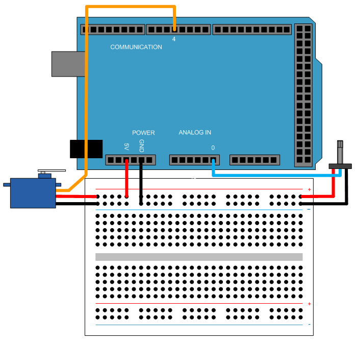
In this task, you will connect your motor to the Arduino board. Servo motors have three wires: power, ground, and signal. Connect them as described below.
1. Connect the power wire (usually red) to the 5V pin.
2. Connect the ground wire (usually black) to the ground pin.
3. Connect the signal wire (usually orange) to digital pin 4. For more information, refer to Pin Mapping for Arduino Timer-Dependent Blocks.

Task 3 - Set Servo Motor Position via Internal Source
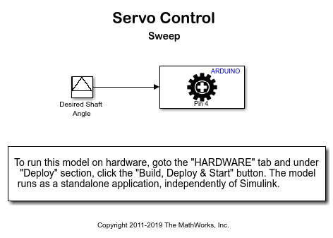
In this task you will set the position of the servo motor shaft using an internal source. The shaft angle will vary between 0 and 180 degrees, up and down.
1. Open the arduino_servocontrol_sweep Simulink model.

2. Notice the Standard Servo Write block. The block sets the new angle of the servo motor shaft every 0.01 second.
3. In your Simulink model, click Simulation > Model Configuration Parameters to open Configuration Parameters dialog box.
4. Select the Hardware Implementation pane and select your required Arduino hardware from the Hardware board parameter list. Do not change any other settings.
5. On the Hardware tab of the Simulink model, in the Mode section, select Run on board and then click Build, Deploy & Start.
6. When the model starts running on the Arduino board, observe the motor shaft position sweeping between 0 and 180 degrees.
Task 4 - Control Servo Motor Position via Potentiometer
In this task you will set the position of the servo motor shaft manually, using a potentiometer. Connect the outer potentiometer terminals to 5V and GND pins on your Arduino board. Connect the middle terminal to analog input pin 0. As your rotate the potentiometer, its resistance changes. As a result, the voltage at the analog input pin changes as well. Your task is to set the servo motor angle proportional to this voltage.

1. In MATLAB®, select HOME > New > Simulink Model.
2. Enter slLibraryBrowser at the MATLAB prompt. This opens the Simulink Library Browser.
3. In the Simulink Library Browser, navigate to Simulink Support Package for Arduino Hardware > Common.
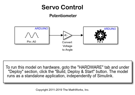
4. Drag the Analog Input block into the model. Double-click the block and set the Pin number to 0, and the Sample time to 0.01 second.
5. Drag the Standard Servo Write block into the model. Double-click the block and set the Pin number to 4.
6. Connect the Analog Input and the Standard Servo Write blocks.
7. From Simulink Math Operations library, drag the Gain block into the model and drop it on the line connecting the Analog Input and the Standard Servo Write block. Double-click the Gain block and set its value to 0.1760 (maximum servo motor displacement in degrees divided by analog input digital resolution i.e. 180/1023).
8. In your Simulink model, click Simulation > Model Configuration Parameters to open Configuration Parameters dialog box.
9. Select the Hardware Implementation pane and select your required Arduino hardware from the Hardware board parameter list. Do not change any other settings.
10. Click OK.
11. On the Hardware tab of the Simulink model, in the Mode section, select Run on board and then click Build, Deploy & Start. The Simulink model will now be deployed to the Arduino hardware.
12. When the model starts running on Arduino board, observe the motor shaft sweeping between 0 and 180 degrees.
If you have trouble creating the model as described above, you can use the arduino_servocontrol_potentiometer model.

Task 5 - Control Servo Motor Position via Photocell
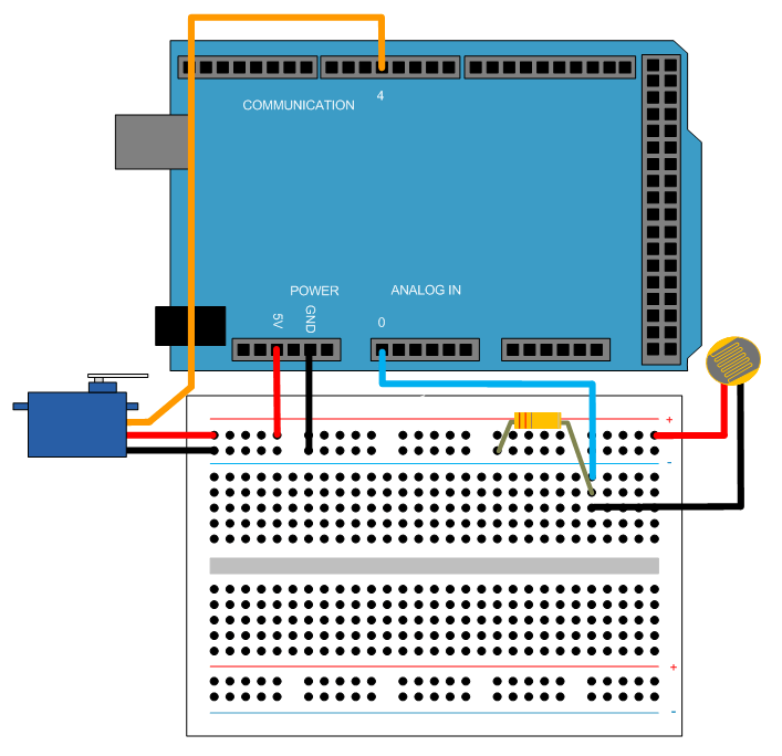
In this task you will create a model that sets the position of the servo motor according to light intensity detected by a photocell. In a dark room the motor shaft should be positioned at 0 degrees, while in a bright room it should be positioned at 180 degrees.
Use a photocell and a resistor instead of the potentiometer you used in Task 4. Connect one end of the photocell to the 5V pin on the Arduino board. Next, connect one end of the resistor to the GND pin on the board. Connect the other ends of the photocell and the resistor together and then to the analog input pin 0 on the board.

The model will be similar to the one used in Task 4.
Other Things to Try
Experiment with other blocks in the Arduino block library. For example:
Use Digital Input block to adjust the motor shaft position depending on the external control signal or signals.
Use Standard Servo Read block to read the motor shaft position and compare it with the desired position.