Estimate Direction of Arrival with Linear Array of Microphones Using Raspberry Pi
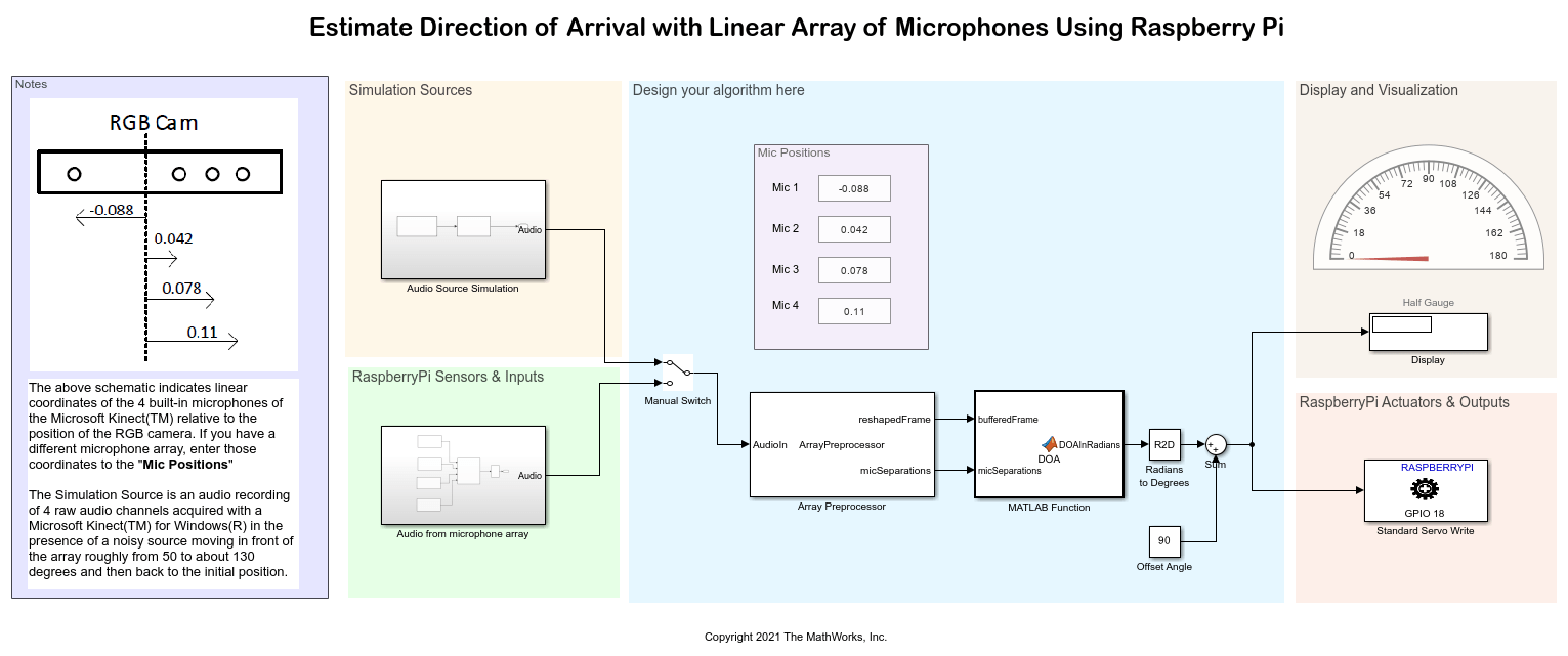
This example shows how to use the Simulink® Support Package for Raspberry Pi® Hardware to estimate the Direction of Arrival (DOA) of a sound source using multiple microphone pairs within a linear array using the Raspberry Pi hardware board. A servo motor is used to point towards the sound source based on the estimated DOA.
Prerequisites
For more information on how to use the Simulink Support Package for Raspberry Pi Hardware to run a Simulink model on Raspberry Pi hardware, see Get Started with Simulink Support Package for Raspberry Pi Hardware.
For more information on how to process audio signals using Raspberry Pi hardware, complete these examples.
- Get Started with Audio Signal Processing Using Raspberry Pi
- Implement Bandpass Filter on Raspberry Pi
- Implement Adaptive Filter for Noise Cancellation Using Raspberry Pi
Required Hardware
Raspberry Pi hardware board
Mobile phone or any source of audio that plays the audio in .wav format
Linear microphone array or four USB microphones arranged linearly in fixed positions
Ethernet cable
Servo motor
Hardware Setup
In the Hardware Setup dialog box, in the Network Settings screen, select
Connect directly to host computerto avoid any network latency.Connect the servo motor to GPIO pin 18 of the Raspberry Pi hardware board.
Configure Simulink Model and Calibrate Parameters
Open the raspberrypi_audio_directionOfArrival Simulink model.

Simulation Sources

In the simulation mode, you can use the prerecorded audio sample Kinect_Recorded.wav that is recorded using Microsoft® Kinect™ for Windows®. This audio file holds a 20 second recording of four raw audio channels acquired with a Microsoft Kinect for Windows in the presence of a noisy source moving in front of the array roughly from –40 to +40 degrees and then back to the initial position. Play this audio file on your host computer. Observe that the audio signal travels from the left headphone to the right and then returns to its starting position.
You can capture your own audio file and select it in the Audio File Read block.
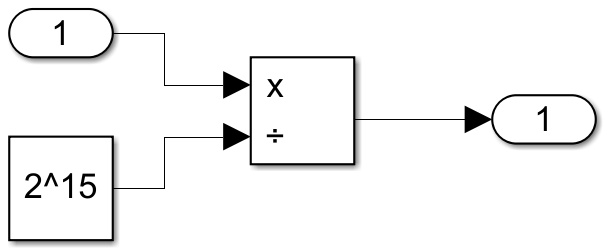
The int16 to single subsystem converts the audio output to single datatype. Double-click the int16 to single subsystem to open it.

The output from the subsystem is one of the inputs to the Manual Switch.
Raspberry Pi Sensors and Inputs
You can use your own linear array of microphones or use four microphones fixed at definite distance from each other. The algorithm in this example works with pairs of microphones independently. It then combines the individual DOA estimates to provide a single live DOA output. The larger the inter-microphone distance the more sensitive the DOA estimate. Use the schematic in the Notes section and mark a point of reference for the microphones in the linear array. For Microsoft Kinect, this point of reference is the relative position of the RGB camera. Note the distance from this point of reference and enter it in the Mic Positions. Enter negative distance values for microphone(s) in one direction from the point of reference, and enter positive distance values in the other direction.

Configure these parameters in the Mic1 ALSA Audio Capture Block Parameters dialog box.
1. Enter the Device name of the USB microphone interfaced with the Raspberry Pi hardware. To know your device name, execute these commands in the MATLAB® Command Window.
a. Establish a connection with the Raspberry Pi hardware.
r = raspberrypi('Raspberry Pi IP address','Username','Password');
b. List input devices connected to the Raspberry Pi hardware.
a = r.listAudioDevices('capture')
a =
struct with fields:
       Name: 'USB-Audio-USBPnPSoundDevice '
     Device: '1,0'
   Channels: {'1'}
   BitDepth: {'16-bit integer'}
SamplingRate: {'44100'  '48000'}
The device ID is listed in the Device property of the function.
Use this format to enter the Device name.
'plughw:<Device ID>'
For example, for the Device property 1,0, enter 'plughw:1,0'.
The plug plugin automatically converts the rate, format, and channel specified in the Block Parameters dialog box of the ALSA Audio Capture block and makes them compatible with the output of the audio device.
2. Select Device Bit Depth of the audio data that refers to the data type in which the audio device reads or sends data.
3. Enter the Number of Channel (C) supported for the audio device.
4. Set Audio sampling frequency to fs.
5. Set Samples per frame to audioFrameLength.
Similarly, configure the parameters for Mic2, Mic3, and Mic4 in the ALSA Audio Capture block.
Note: To use Microsoft Kinect to capture the source of sound, configure the Audio from microphone array subsystem in this manner.

Design your algorithm here
In the Array Preprocessor system object, you can enter the positions for the microphones and configure the mic pairings. The Array Preprocessor system object is specific to this example only.
Configure these parameters in the Array Preprocessor system object.
Enter the inter-microphone spatial distances in the Microphone positions as spatial coordinates parameter. Enter these values in meters.
Enter the microphone pairings in the Mic pairs parameter. For example, the value
[ 1, 4; 1, 3; 1, 2 ]indicates that the first microphone is paired with all the other microphones as the inter-microphone distance is the largest.Set Output Buffer Length to
64.Set Simulate using to
Code generation.
The reshaped frame of the audio signal and the distance between the microphone pairs are given as inputs to the MATLAB Function block that determines the DOA. This DOA is in radians. Use the Radians to Degrees block to convert the DOA from radians to degrees. This value in degrees ranges between –90 to +90 degrees. An offset of +90 is added to this value to range this value from 0 to 180 degrees for interfacing a servo motor with the Raspberry Pi hardware.
Display and Visualization
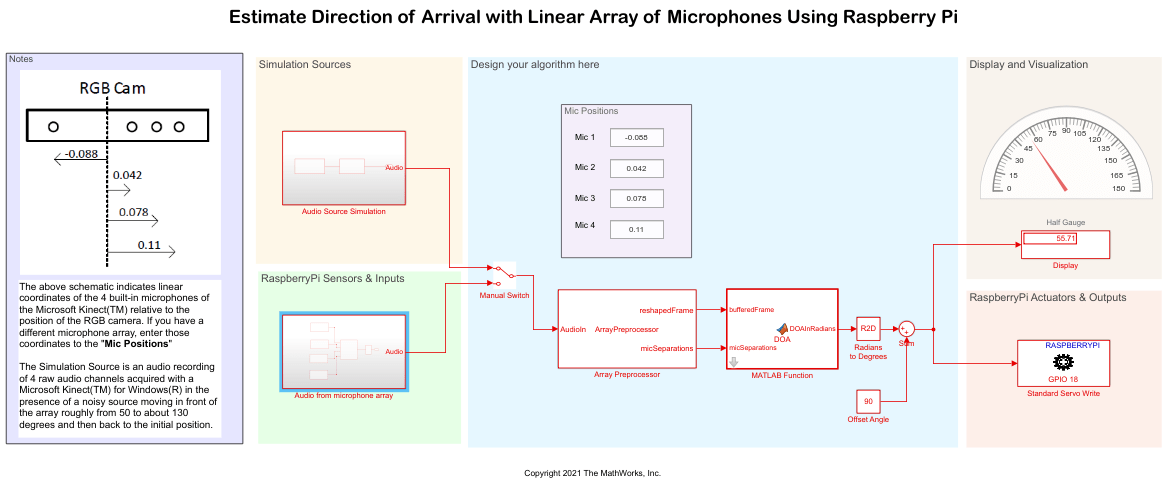
The Display and Half Gauge blocks displays the DOA in degrees.
Raspberry Pi Actuators and Outputs
The Standard Servo Write block points towards the sound source and determine the DOA. This block is configured to its default parameters.
Run Simulink Model
In the Design your algorithm area, position the Manual Switch to the output from the Simulation Sources area.
On the Simulation tab of the Simulink model, click Run.
Observe the Display and Half Gauge blocks displaying the DOA in degrees.

Deploy Simulink Model
In the Design your algorithm area, position the Manual Switch to the output from the Rapsberry Pi Sensors and Inputs area.
On the Hardware tab of the Simulink model, in the Mode section, select Run on board and then click Monitor & Tune. Observe the servo motor pointing towards the source of sound.
Other Things to Try
Use different microphone pairings and observe the DOA for the source of audio.