Main Content

Ultrasonic Sensor

Measure distance between ultrasonic sensor and object

Since R2022b

Add-On Required: This feature requires the Simulink Support Package for Raspberry Pi Hardware add-on.

  • Ultrasonic Sensor block

Libraries:
Simulink Support Package for Raspberry Pi Hardware / Sensors

Description

The Ultrasonic Sensor block outputs the distance between the ultrasonic sensor connected to the hardware and the nearest object in front of the sensor. The block outputs the distance as a double-precision value, in meters. If the object is placed beyond the range of sensor detection, the block outputs 0.

If you simulate a model that contains the Ultrasonic Sensor block without connecting the hardware, the block outputs zeros. For more information, see Block Produces Zeros or Does Nothing in Simulation.

Ports

Output

expand all

The port outputs the distance between the ultrasonic sensor connected to the hardware and the nearest object in front of the sensor. The block outputs the distance in meters. If the object is placed beyond the range of sensor detection, the port outputs 0.

Data Types: double

Parameters

expand all

Select the Raspberry Pi® hardware board to which the ultrasonic sensor is connected. For information about the digital pin numbers on the hardware, click View pin map.

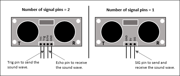
Select the number of signal pins on the ultrasonic sensor to send and receive sound waves.

  • 1 — If the ultrasonic sensor has only one signal pin, SIG, select 1.

  • 2 — If the ultrasonic sensor has two separate signal pins, Trig and Echo, select 2.

Select the digital pin on the hardware to which the Trig pin of the ultrasonic sensor is connected. For information about the digital pin numbers on the hardware, click View pin map.

Dependencies

The Trigger pin parameter appears only when you set the Number of signal pins parameter to 2.

Select the digital pin on the hardware to which the Echo pin of the ultrasonic sensor is connected. For information about the digital pin numbers on the hardware, click View pin map.

Dependencies

The Echo pin parameter appears only when you set the Number of signal pins parameter to 2.

Select the digital pin on the hardware to which the SIG pin of the ultrasonic sensor is connected. For information about the digital pin numbers on the hardware, click View pin map.

Dependencies

The Signal pin parameter appears only when you set the Number of signal pins parameter to 1.

Specify how often the block reads distance using the ultrasonic sensor, measured in seconds.

When specifying Sample time, verify these settings to avoid task overrun:

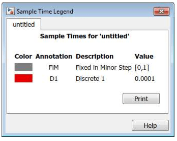
  1. The Sample time parameter must be equal to the model base rate. To view the model base rate, select Display > Sample Time > All on the model toolbar. In the Sample Time Legend dialog box, the value corresponding to the red box is the base rate of the model.

  2. The Sample time parameter and the model base rate must be greater than the total time required by the sensor to transmit and receive the sound wave. For example, if the object is placed 0.1 meters away from the sensor, the Sample time parameter specified must be greater than 0.000301 seconds.

    For information on how to calculate the travel time of the sound wave, see Calculate Travel Time of Sound Wave.

More About

expand all

Version History

Introduced in R2022b