Enable Secondary SPI Bus of Raspberry Pi Hardware
Raspberry Pi® hardware uses the SPI0 as the default bus interface to communicate with various SPI peripherals such as sensor and actuators.
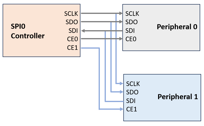
The SPI0 Controller on Raspberry Pi hardware can drive two SPI peripheral devices that uses these four pins.
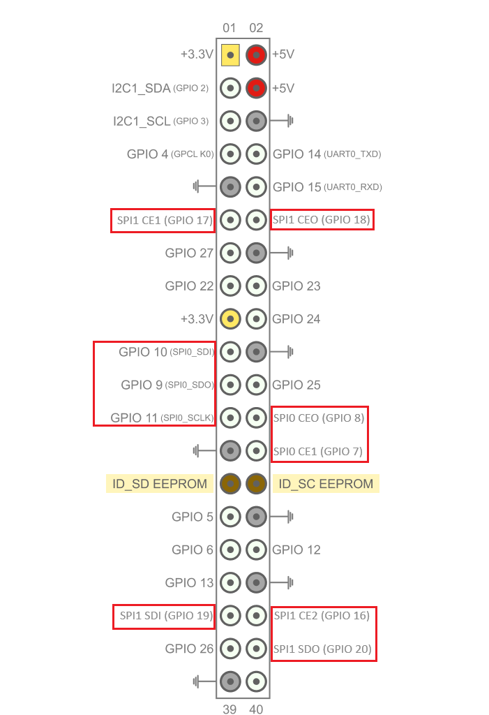
GPIO 11 (SPI0_SCLK) outputs a serial clock signal to synchronize communications.
GPIO 10 (SPI0_SDO) outputs data to the SPI peripheral device.
GPIO 9 (SPI0_SDI) receives data from the SPI peripheral device.
GPIO 8 (SPI0_CE0) enables one SPI peripheral device.
GPIO 7 (SPI0_CE1) enables the other SPI peripheral device.

For more information, see Raspberry Pi SPI Interface.
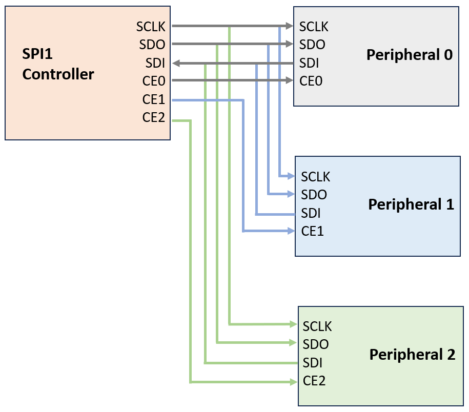
Using the Simulink® Support Package for Raspberry Pi Hardware, you can enable the SPI1 bus interface to connect multiple SPI peripherals with the same address to your Raspberry Pi hardware. The SPI1 Controller on Raspberry Pi hardware can drive three SPI peripheral devices.

The SPI1 Controller on Raspberry Pi hardware uses these four pins.
GPIO 21 (SPI1_SCLK) outputs a serial clock signal to synchronize communications.
GPIO 20 (SPI1_SDO) outputs data to the SPI peripheral device.
GPIO 19 (SPI1_SDI) receives data from the SPI peripheral device.
GPIO 18 (SPI1_CE0) enables first SPI peripheral device.
GPIO 17 (SPI1_CE1) enables second SPI peripheral device.
GPIO 16 (SPI1_CE2) enables third SPI peripheral device.

Follow these steps to enable the SPI1 bus interface on your Raspberry Pi hardware.
On your Raspberry Pi terminal, execute this command to open the
/boot/config.txtfile in a text editor.nano /boot/config.txt
In the
config.txtfile, add this device tree parameter in a new line.dtoverlay=spi1-3cs
This command follows this format:
spi(bus number)-(number of chip select
            pins)cs
So, SPI1 bus interface uses three chip select pins from 0 through 2.
Save the
config.txtfile.Reboot your Raspberry Pi.
reboot
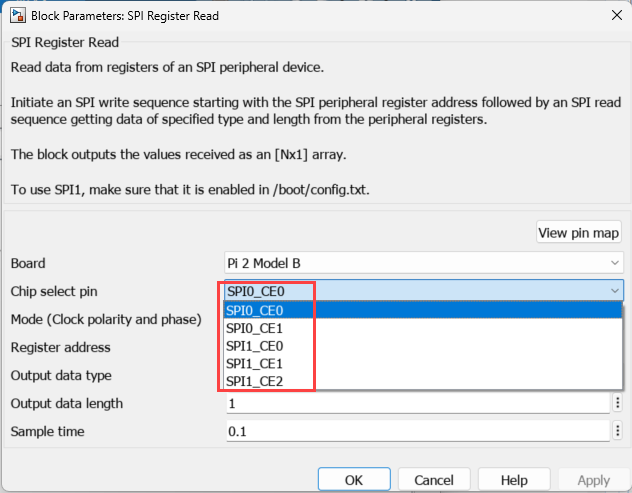
Open MATLAB®. From the support package, open a block that utilizes SPI to communicate with peripherals, for example open the SPI Register Read block. Observe that the Chip select pin parameter is populated with options
SPI0_CE0,SPI0_CE1,SPI_CE0,SPI1_CE1,SPI1_CE2.
Note
Prefer using SPI0 module over SPI1 module especially when only a single SPI interface is needed.
In a Simulink model, after you enable both the SPI0 and SPI1 bus interfaces, you can configure the blocks from the Simulink Support Package for Raspberry Pi Hardware for both SPI0 and SPI1.
While using any SPI block in a Simulink model, ensure that the Raspberry Pi hardware pins associated with the SPI bus interfaces are not being used other non–SPI blocks to avoid any unexpected behavior.
See Also
Raspberry Pi SPI Interface | Enable Secondary I2C Bus of Raspberry Pi Hardware | SPI Controller Transfer | SPI Register Read | SPI Register Write