Add Enumerated Inputs, Outputs, and Parameters to a MATLAB Function Block
When you add enumerated inputs, outputs, or parameters to a MATLAB Function block, follow these guidelines:
For inputs, inherit the type from the enumerated type of the connected Simulink® signal or specify the enumeration explicitly.
For outputs, specify the enumerated type explicitly.
For tunable parameters, specify the enumerated type explicitly. For nontunable parameters, derive the properties from an enumerated parameter in a parent Simulink masked subsystem or enumerated variable defined in the MATLAB® base workspace.
To add enumerated data to a MATLAB Function block:
In the Symbols pane, click the Create Data button
 . In the Name field, enter a name for
the enumerated data.
. In the Name field, enter a name for
the enumerated data.For parameters, the name must match the enumerated masked parameter or workspace variable name.
In the Property Inspector, in the Type field, specify an enumerated type.
For an explicit enumerated type, set Type to
Enum: <class name>. Replace<class name>with the name of an enumerated data type that you defined in a MATLAB file on the MATLAB path.The Complexity field is not visible because enumerated data types do not support complex values.
For inputs, to inherit the enumerated type from a connected Simulink signal, set Type to
Inherit: Same as
                  Simulink
.
Enumerations in a MATLAB Function Block
This example shows how MATLAB Function blocks exchange enumerated data with other Simulink blocks. The model uses enumerations to represent the modes of a device that controls the colors of an LED display. The MATLAB Function block receives an enumerated input signal that represents the mode. The enumerated output signal represents the color that the LED displays.
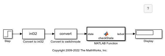
In this model, the Step block provides the source of the on/off signal. This block outputs an initial value of 0 (off) and, after 10 seconds, steps up to a value of 1 (on). A pair of Data Type Conversion blocks convert this signal from type double to type int32, and then from int32 to the enumerated type switchmode. The parameters in the second Data Type Conversion block have these settings:
Output minimum:
[]Output maximum:
[]Output data type:
Enum:switchmode
The MATLAB Function block evaluates the enumerated input state to determine the value of the enumerated output ledval. state inherits its enumerated type switchmode from the incoming Simulink signal, while ledval has the type Enum:led. Finally, a Display block displays the value of ledval.
View the Enumeration Class Definitions
The switchmode enumeration represents the allowed modes for the input to the MATLAB Function block.
classdef switchmode < Simulink.IntEnumType
    enumeration
        OFF(0),
        ON(1),
    end
end
The led enumeration represents the colors that the MATLAB Function block outputs.
classdef led < Simulink.IntEnumType
    enumeration
        GREEN(1),
        RED(8),
    end
end
Both enumeration classes inherit from the built-in type Simulink.IntEnumType and reside on the MATLAB path.
Inspect the MATLAB Function Block
Open the MATLAB Function block. The function checkState uses enumerations to activate an LED display based on the state of a device. The function lights a green LED display to indicate the ON state and a red LED display to indicate the OFF state.
function ledval = checkState(state)
    if state == switchmode.ON
     ledval = led.GREEN;
else
     ledval = led.RED;
end
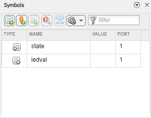
In the Function tab, click Edit Data to view the enumerated inputs and outputs specified in the MATLAB Function block. The Symbols pane displays the input state and the output ledval.
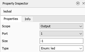
When using enumerations for outputs, you must explicitly refer to the enumeration class definition in the Type property of the variable. Click either of the variable names to view the properties in the Property Inspector. In this example, the Type property for state is Inherit: Same as Simulink. The Type property for ledval is Enum: led.
Simulate the Model
When you simulate the model, the Display block displays the state of the LED display. If you simulate the model for less than 10 seconds, the state is OFF and the Display block displays RED. If you simulate the model for more than 10 seconds, the state is ON and the Display block displays GREEN.
See Also
MATLAB Function | MATLAB Function Block Editor