连接模块
通过连接模型中的各模块以在这些模块之间建立关系。
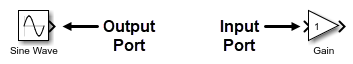
您可以使用信号线连接大多数模块。信号线连接到模块上的端口。在仿真期间,信号从输出端口传输到连接的输入端口。
您可以通过创建分支信号线将信号从一个模块的输出端口发送到多个模块的输入端口。
对于某些模块,您可以更改模块上的输入端口数量。例如,要在同一图上绘制多个信号,您可以增加 Scope 模块上的输入端口数量。
有关更改信号线布局的信息,请参阅配置模型布局。有关如何对信号线加标签的信息,请参阅配置模型元素名称和标签。
您可以通过捆绑信号来简化模块图。有关捆绑信号的信息,请参阅将信号或消息组合到虚拟总线中。
相关模块无需信号线即可连接。有关如何连接相关模块的信息,请参阅在不使用信号线的情况下连接模块。
用信号线连接模块
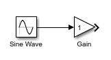
要使用一条信号线连接两个模块,请点击一个模块的输出端口上的端口符号  并将其拖动到另一个模块的输入端口。
您可以使用以下快捷方式连接模块:
要在不拖动信号线的情况下连接模块,请执行以下操作:
垂直对齐要连接的输出端口和输入端口,中间没有其他组件。如果端口已对齐,请移动其中一个模块以打破对齐,然后重新对齐它们。当您释放为对齐端口而移动的模块时,会出现连接预览。
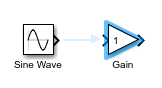
要建立连接,请点击预览。
要在不拖动信号线或对齐端口的情况下连接模块,请执行以下操作:
点击要连接的输出端口的端口符号。端口提示符号
 会出现在可连接到的其他组件的输入端口上。
要查看连接预览,请将鼠标指针悬停在要连接的输入端口的端口提示符号上。
要建立连接,请点击预览。

要在不拖动信号线或对齐端口的情况下将多个模块连接到单个模块,请执行以下操作:
选择要连接其输出端口的模块,例如通过左键点击并拖动以在这些模块周围形成一个选择框。
按 Ctrl 键并点击要连接其输入端口的模块。
要将一个模块的输入端口和输出端口都连接到一条现有信号线,请点击该模块并将其拖到该信号线上。定位模块,使端口符号
位于信号线上。当输出端口符号消失且输入端口符号变为实心箭尖时,释放鼠标指针。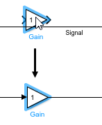
要使一个信号线段变为对角线,请按 Shift 键并拖动连接到另一个信号线段的顶点。

将单个输出端口连接到多个输入端口
要将一个输出端口连接到多个输入端口,请先将一个输入端口连接到该输出端口,然后建立分支信号线以连接到其他输入端口。
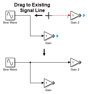
要建立分支信号线,请按 Ctrl 键,然后点击现有信号线并将其拖动到要连接的模块的输入端口。
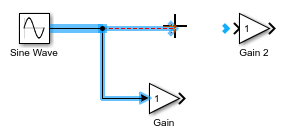
提示
要建立分支信号线,您也可以点击未连接的输入端口的端口符号并将其拖到现有信号线上。
将多个模块的输出端口连接到单个模块
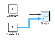
某些模块可以在其输入端口侧连接多条信号线。例如,要在一个图上绘制多个信号,您可以将多个模块的输出端口连接到单个 Scope 模块。
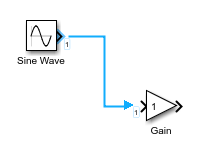
要将多个模块的输出端口连接到单个模块,请从要连接的每个输出端口将信号线拖动到单个模块的输入端口侧(左边缘)。当模块图标变为蓝色且端口号出现时,释放指针。系统会自动创建一个输入端口以连接该信号线。
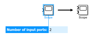
如果要连接其输出端口的模块尚未在模型中,要增加单个模块上的输入端口数量,请执行以下操作:
将指针悬停在该模块的输入端口侧(左边缘),直到指针旁边出现加号。

然后,点击并将指针拖离模块。将出现一条虚线信号线,您可以将其连接到另一个模块的输出端口。

要删除一个输入端口,请点击其端口符号并按 Delete 键。
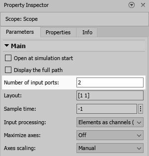
要指定一个模块的输入端口数量,请使用“模块参数”对话框或属性检查器的参数选项卡。
提示
对于某些模块,您可以在将模块添加到模型时输入输入端口数量。
连接子系统
要将信号发送到子系统中,该子系统必须包含与要发送到该子系统的信号数量相同的输入端口。
要从子系统接收信号,该子系统必须包含与要从子系统接收的信号数量相同的输出端口。
当您将一个空白子系统添加到模型时,该子系统默认包含一个输入端口和一个输出端口。
要连接子系统,请执行以下操作:
要进入子系统,双击 Subsystem 模块。

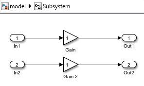
在子系统内部,添加所需数量的输入端口和输出端口。
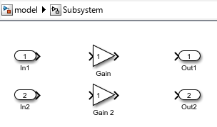
在子系统内部,将输入端口和输出端口连接到子系统。
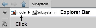
要在模型层次结构中向上导航一个层级,请在 Simulink® 画布顶部的资源管理器栏中,点击 Subsystem 模块名称左侧的层级名称。
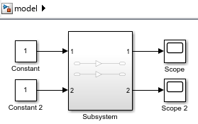
将要发送到子系统中的信号的信号线连接到 Subsystem 模块的输入端口。
Subsystem 模块上的每个输入端口对应子系统内部的一个 Inport 模块。您可以通过端口号判断 Subsystem 模块上的哪个输入端口对应子系统内部的哪个 Inport 模块。
将要从子系统接收的信号的信号线连接到 Subsystem 模块的输出端口。
Subsystem 模块上的每个输出端口对应子系统内部的一个 Outport 模块。
提示
要避免手动连接子系统,请在要添加 Subsystem 模块的模型层次结构层级中构建子系统的内容。然后,将内容转换为子系统:
通过在画布上点击并拖动指针绘制包含这些组件的矩形来选择子系统组件。
将鼠标暂停在出现的省略号上。
在展开的操作栏中,点击创建子系统。
转换为子系统会自动添加并连接子系统的输入端口和输出端口。
将端口模块连接到子系统
当您将端口模块连接到 Subsystem 模块时,自定义端口或元素名称将替换默认端口或元素名称。
假设您有:
Inport 模块,命名为
Control和In2In Bus Element 模块,标签为
Sinusoidal.Sine和InBus.signal1Subsystem 模块,端口名称为
In1、Sensor、InBus和Pulse
Subsystem 模块图标显示具有默认名称 In1 的 Inport 模块的端口号。

当您连接端口时:
自定义端口名称将替换对应的默认端口名称。例如,当您将名为
Control的 Inport 模块连接到标签为1的子系统端口时,子系统端口名称和对应的 Inport 模块名称将从In1更改为Control。同样,当您将名为In2的 Inport 模块连接到名为Sensor的子系统端口时,Inport 模块名称将从In2更改为Sensor。自定义元素名称将替换对应的默认端口名称。例如,当您将标签为
Sinusoidal.Sine的 In Bus Element 模块连接到名为InBus的子系统端口时,子系统端口名称将从InBus更改为Sine。 (自 R2026a 起)自定义端口名称将替换对应的默认元素名称。例如,当您将标签为
InBus.signal1的 In Bus Element 模块连接到名为Pulse的子系统端口时,In Bus Element 模块元素名称将从signal1更改为Pulse。 (自 R2026a 起)

如果加载了引用模型,相同的行为也适用于连接到 Model 模块端口的端口。Model 模块端口不受影响。

在不使用信号线的情况下连接模块
相关模块无需信号线即可相互连接。
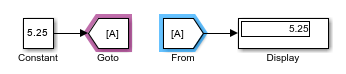
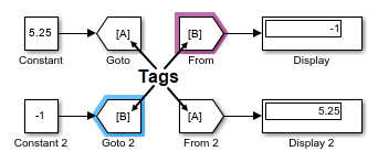
例如,Goto 和 From 模块是相关模块,您无需信号线即可使用它们发送信号。进入 Goto 模块的信号无需通过信号线即可退出 From 模块。
要连接相关模块,请使用“模块参数”对话框或属性检查器的参数选项卡。
提示
要检查两个或更多相关模块是否已连接,请选择其中一个模块。所有与选定模块连接的相关模块会以紫色突出显示。
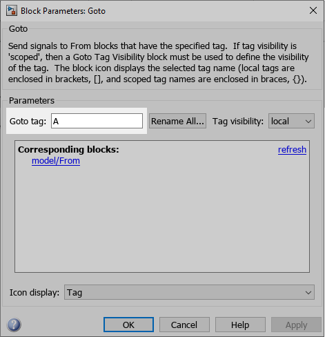
某些相关模块使用标记进行连接。例如,所有具有相同标记的 Goto 和 From 模块都会连接。
您可以在“模块参数”对话框或属性检查器的参数选项卡中为这些模块设置标记。
Dashboard 和 Customizable Blocks 库中的模块也是相关模块。您可以将这些库中的显示模块连接到信号。您可以将控制模块连接到模块参数或变量。有关如何连接 Dashboard 模块的信息,请参阅Connect Dashboard Blocks to Simulink Model。
将信号线转换为 Goto 和 From 模块,反之亦然
您可以通过用 Goto 和 From 模块替换冗长的信号线来简化模型图。但是,当您要跟踪信号路径时,查看信号线会很有用。
您可以将信号线和虚拟总线转换为 Goto 和 From 模块集,并且可以将 Goto 和 From 模块集转换为信号线。Goto 和 From 模块组是一组连接的 Goto 和 From 模块,这意味着这些模块具有相同的标记。
要转换的模型元素必须满足以下条件:
信号线、总线或模块已完全连接。
信号线、总线或模块都位于模型层次结构中的同一位置,即:要么都在层次结构的顶层,要么都在同一组件中。
信号线或总线未连接到任何 Goto 或 From 模块。
在转换过程中,软件会忽略不符合这些条件的模型元素。无论模块标记是否可见,您都可以执行转换。
要将 Goto 模块及其连接的所有 From 模块转换为信号线,请选择 Goto 模块。要将 From 模块及其连接的 Goto 模块转换为信号线,请选择 From 模块。将指针悬停在选定模块上方出现的省略号上。在展开的操作菜单中,选择转换为信号。或者,选择 Goto 或 From 模块,然后在 Simulink 工具条的 Goto 或 From 选项卡上,点击转换为信号。
要将信号线或总线转换为 Goto 和 From 模块组,请选择该信号线或总线。将鼠标暂停在出现的省略号上。在展开的操作菜单中,选择转换为 Goto 和 From 模块。或者,选择信号线或总线,然后在工具条的信号选项卡上,点击转换为 Goto/From。
要同时将多个 Goto 模块及其所有连接的 From 模块转换为信号线,请按住 Shift 键并点击各模块,或通过拖动在这些模块周围形成一个选择框来选择所有 Goto 模块。在 Simulink 工具条的 Goto 选项卡上,点击转换为信号。
如果一个 Goto 模块具有多个具有相同标记的 From 模块,要将其中部分 From 模块转换为信号线,请选择您要转换的 From 模块。在工具条的 From 选项卡上,点击转换为信号。选定 From 模块将转换为连接到对应 Goto 模块输出信号线的信号线。Goto 模块不会转换为信号线。
要同时将多条信号线或总线转换为 Goto 和 From 模块组,请通过按住 Shift 键并点击或通过拖动以形成一个选择框来选择这些信号线或总线。在工具条的信号选项卡上,点击转换为 Goto/From。
注释掉和注释直通模块
您可以通过注释掉或注释直通模块来将模块排除在仿真之外,而无需从模型中物理删除这些模块。
注释掉:将选定模块排除在仿真之外。信号终止并接地。
注释直通:将选定模块排除在仿真之外。信号通过。要注释直通一个模块,该模块必须具有相同数量的输入端口和输出端口,并且没有控制端口或连接端口。
注意
不支持注释掉或注释直通以下 Simulink 模块:
Inport
Outport
Connection Port
Argument Inport
Argument Outport
Data Store Memory
Goto Tag Visibility
不支持注释直通 Signal Generator 模块。
要注释掉某模块,请选择该模块。在出现的操作栏中,点击注释掉。
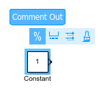
要注释直通模块,请右键点击该模块,然后点击“注释直通”按钮  。
。
提示
或者,选择该模块并按:
Ctrl+Shift+X 将其注释掉
Ctrl+Shift+Y 将其注释直通