Model Wireless Message Communication with Packet Loss and Channel Failure
This example shows how to model wireless message communication with packet loss and channel failure by using Simulink® messages, Stateflow®, and SimEvents®.
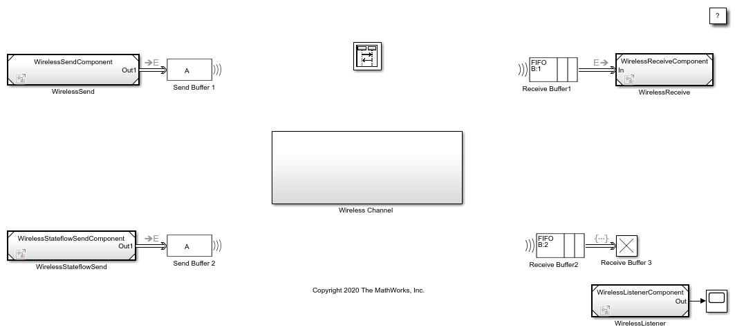
In this model, there are two components that send messages and two components that receive messages. The messages are transmitted using a shared wireless channel with a transmission delay. A Stateflow chart models message-sending logic in a wireless component and SimEvents blocks model wireless message transmission, channel failure, and packet loss.

For an overview about messages, see Simulink Messages Overview.
Create Components to Send and Receive Messages
In the model, there are two software components that output messages, WirelessSend and WirelessStateflowSend.
In the WirelessSend component, the Sine Wave block is the signal source. The Sine Wave block generates a sine wave with an amplitude of 1. The block Sample time is set to 0.1. The Send block converts the signal to a message that carries the data of the signal value. The WirelessSendComponent is connected to Send Buffer 1.
In the WirelessStateflowSend component, another Sine Wave block generates a sine wave signal and a Noise block is used to inject noise into the signal. The Noise block outputs a signal whose values are generated from a Gaussian distribution with mean of 0 and variance of 1. The Stateflow chart represents a simple logic that filters a signal and decides whether to send messages. The StateflowSend component sends messages to Send Buffer 2.
In the model, there are two software components that receive messages, WirelessReceive and WirelessListener.
In the WirelessReceive component, a Receive block receives messages and converts message data to signal values. The component is connected to Receive Buffer 1.
In the WirelessListener component, there is a Simulink Function block that runs the onOneMessage(data) function. When a message arrives at Receive Buffer 3, the Simulink Function block takes the argument data, which is the value from message data, as the input signal. In the block, the data values are multiplied by 2. The block outputs the new data value.
To learn more about creating these components, see Build a Shared Communication Channel with Multiple Senders and Receivers.
Model Wireless Message Communication Using Multicasting
The WirelessSend and WirelessStateflowSend components send messages to Send Buffer 1 and Send Buffer 2, which are SimEvents Entity Multicast blocks that can wirelessly transmit messages. The Transmission Buffer block is a SimEvents multicast receive queue that can receive messages sent by Send Buffer 1 and Send Buffer 2.
To achieve this wireless communication between Send Buffer 1, Send Buffer 2, and the Transmission Buffer block that is inside the Wireless Channel block:
In the Send Buffer 1 and Send Buffer 2 blocks, set the Multicast tag parameter to
A.In the Transmission Buffer block, set the Multicast tag parameter to
A.

The Multicast tag parameter defines from which Entity Multicast blocks the messages are received.
Model Channel Failure
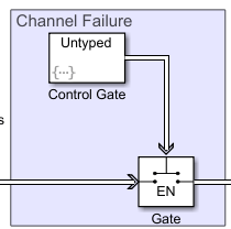
A SimEvents Entity Gate block is used to model channel failure. The block has two input ports. One input port is for incoming messages from Transmission Buffer. The second input port is a control port to decide when to open the gate.

Set the Operating mode parameter for the Gate block to Enable gate. In this mode:
The block opens the gate and permits messages to advance when it receives an entity carrying a value that is greater than
0from its control port. This represents an operational channel.
The block closes the gate and blocks messages passing if an entity carries data whose value is less than or equal to
0. This represents a channel failure.
To control the Gate block, you can use the SimEvents Entity Generator block, which is labeled Control Gate in this example, to generate entities carrying different data values.
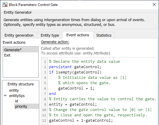
In the Control Gate block, in Event actions, in the Generate action field, the code below is used to generate entities to open and close the Gate block. Initially, entity data is 1 and the gate is open and the channel is in operational state. When a new entity is generated, its value changes to 0, which closes the gate. Every generated entity changes the status of the gate from open to closed or from closed to open.

In the Control Gate block, in the Intergeneration time action field, the code below is used to represent the operational and failed state of the channel. The code initializes the channel as operational. dt is the entity intergeneration time and is used to change the status of channel because each generated entity changes the status of the Gate block.

In the code, the repair time is generated from a uniform distribution that takes values between 0 and 10. The time interval between the failures is generated from another uniform distribution that takes values between 0 and 50.
Model Packet Loss
To model the packet loss, a SimEvents Entity Output Switch block is used.
The block has two input ports. One input port accepts messages. The other input port accepts entities that determine the output port selection. If the entity is set to 1, the block selects output port 1 to forward messages to the Wirelessly Share Messages block. If the entity is set to 2, the block selects output port 2, which is connected to an Entity Terminator block that represents packet loss.

In the Output Switch block:
The Number of output ports is set to
2.
To determine which output is selected, the Switching criterion is set to
From control portand Initial port selection is set to1.
To model a 0.1 probability of packet loss, in the Probabilistic Packet Loss block, select the Event actions tab, and in the Generate action field includes this code:
persistent rngInit;
if isempty(rngInit)
    seed = 12345;
    rng(seed);
    rngInit = true;
end
% Pattern: Uniform distribution
% m: Minimum, M: Maximum
m = 0; M = 1;
x = m + (M - m) * rand;
% x is generated from uniform distribution and
% takes values between |0| and |1|.
if x > 0.1
   % Entity carries data |1| and this forces Output switch to select
   % output |1| to forward entities to receive components.
   entity  = 1;
else
   % Entity carries data |2| and this forces Output switch to select
   % output |2| and this represents a packet loss.
    entity = 1;
end
This means that entities entering the control port have a 0.9 probability of being set to 1, which makes the block output messages to the Wirelessly Share Messages block.
Simulate the Model and Review results
Simulate the model.
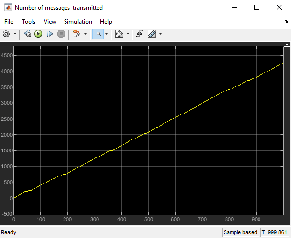
Open the Scope block connected top the Transmission Buffer block. The block displays the total number of messages transmitted through the shared channel.

4255 messages are transmitted through the channel.

The plot also displays the channel failures. For example, zoom into the first 100 seconds. Observe that the channel failure occurs between 40 and 49 during which message transmission is blocked.

Open the Data Inspector to visualize the entities that control the Gate. Entity data changes from 1 to 0 for each generated entity.

To see the number of lost messages, open the Scope block connected to the Packet Loss block.

409 messages are lost during transmission. This is 9.6 percent of the messages.

See Also
Sine Wave | Send | Receive | Queue | Entity Terminator (SimEvents) | Entity Output Switch (SimEvents) | Entity Gate (SimEvents) | Entity Multicast (SimEvents)