Use Virtual Buses with Message Elements for Component Communication
This example shows how to model message-based communication between software components that communicate using virtual buses with message elements.
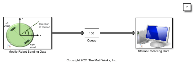
The model in this example is a flat non-holonomic robot that can move or rotate with the help of two wheels, similar to a home vacuuming robot. This model assumes that the robot moves in one of two ways:
Linear — Both wheels turn in the same direction with the same speed, and the robot moves linearly.
Rotational — The wheels turn in opposite directions with the same speed, and the robot rotates in place.
To learn how to create the model for the robot, see System Definition and Layout.
In this example, the robot sends its velocity in x- and y- directions to the base station and its relative angle (direction of motion) values to a base station. The station's data consumption rate is slower than the data sent by the robot. A Queue block is used as a message buffer.
Send Virtual Bus Message Elements with Nonvirtual Bus Payload
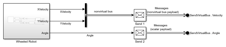
In this model, components that represent the mobile robot and the station communicate using virtual buses with message elements. XVelocity and YVelocity represent x and y components of the robot's velocity, respectively. Angle represents the robot's relative angle to the x-axis.
In the Mobile Robot Sending Data component, XVelocity and YVelocity signals are combined into the nonvirtual bus Velocity. The Send 1 block creates messages with velocity data as the payload. In this framework, messages provide asynchronous event-based communication between components. Using messages with a nonvirtual bus payload allows the software to treat Velocity as data containing XVelocity and YVelocity as its fields. Therefore, each message includes XVelocity and YVelocity data.
The Send 2 block creates messages with Angle data as the payload. The Out Bus Element blocks labeled SendVirtualBus.Velocity and SendVirtualBus.Angle specify Velocity and Angle as elements of the virtual bus SendVirtualBus. You can combine messages into a virtual bus to create message send interfaces. In the message receive interfaces, you can access the bus as a whole or select specific messages from the bus. For more information about message send and receive interfaces, see Simulink Messages Overview.
The components communicate via the following:
The model pre-load function
load('Velocity.mat')loads theVelocitybus object to the workspace.A Bus Creator block groups
XVelocityandYVelocityinto a nonvirtual bus defined by theVelocitybus object.The Send 1 block creates messages with
Velocityas the payload.The Out Bus Element block labeled
SendVirtualBus.Velocitycreates the virtual busSendVirtualBuswith theVelocityelement. In the block, Data type is set toBus: Velocity, and Data mode is set tomessage.

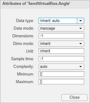
The Out Bus Element block labeled
SendVirtualBus.AnglespecifiesAngleas a message element ofSendVirtualBus.
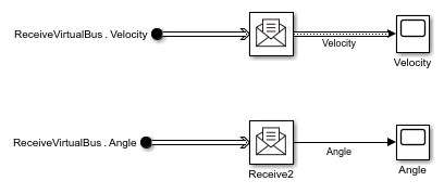
The Station Receiving Data component receives virtual buses and selects the message elements using the In Bus Element block. Receive blocks convert messages to signals for processing and visualization.
For more information about creating send and receive interfaces for messages with a nonvirtual bus payload, see Send and Receive Messages Carrying Bus Data.
You can simulate the model or generate code for both Mobile Robot Sending Data component and Station Receiving Data component. For more information, see Generate C++ Messages to Communicate Data Between Simulink and an Operating System or Middleware (Embedded Coder).
Simulate the Model and Review Results
Simulate the model. Observe the communicated velocity of the robot in x and y directions. The robot moves in y direction because its velocity in x direction is constant and 0.
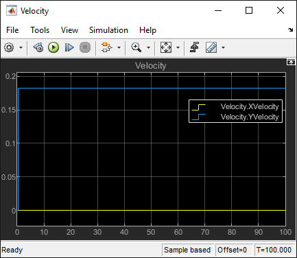
Observe the robot's constant relative angle in radians. The angle pi/2 confirms the motion in the y direction.

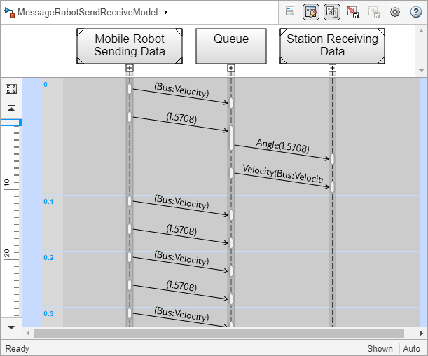
Use the Sequence Viewer tool to display the virtual buses communicated between the robot and the station. To open the Sequence Viewer tool, in the Simulink® toolstrip, on the Simulation tab, under Review Results, select Sequence Viewer.
The Sequence Viewer window displays the virtual bus transitions from the Mobile Robot Sending Data component to the Queue block and from the Queue block to the Station Receiving Data component.
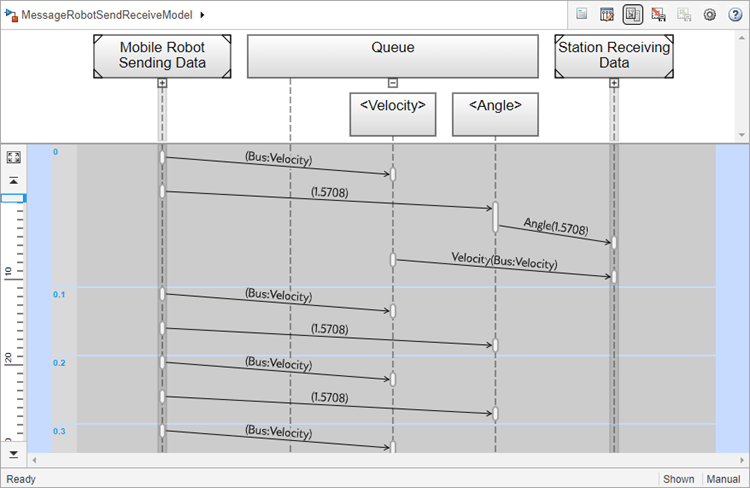
Queue Expansion
Expand the Queue lifeline in the Sequence Viewer window. Observe that the Queue block expands to two Queue blocks that provide storage for two virtual bus message elements, Velocity and Angle. The additional Queue block has the same configuration and capacity as the original Queue block. For more information about the Queue block, see Use a Queue Block to Manage Messages.
Visualize Virtual Buses with Message Elements
Animation allows you to observe the virtual buses communicated between the robot and the station during the simulation. To turn on animation, from the toolstrip, on the Debug tab, in the Event Animation section, select the Animation Speed.
You can specify Slow, Medium, or Fast animation speed. Select None to turn off the animation. For more information about animation and message visualizations, see Animate and Understand Sending and Receiving Messages.

The animation highlights virtual buses sent from the robot to the Queue block and from the Queue block to the station.

Pause the animation and point to the magnifying glass on the Queue block to open the Storage Inspector. The Storage Inspector displays the bus elements and message data.

Virtual Buses with Message Elements in Architecture Models
You can model message-based communication between software components by first designing your system from the architecture level using System Composer™. The architecture models in System Composer support Simulink models with message input and output as component behavior.
Below is an example illustration that shows the design of architecture components to represent the mobile robot and the station. The Simulink models used in the example above, MessageSendRobotModel and MessageReceiveRobotModel, are attached to these components as component behaviors. When you compile the model, a LIFO queue of capacity 1 is automatically inserted to the architectural model for simulation. Designing message interfaces from the architecture level requires a System Composer license.

See Also
Topics
- Send and Receive Messages Carrying Bus Data
- Establish Message Send and Receive Interfaces Between Software Components
- Model an Ethernet Communication Network with CSMA/CD Protocol
- Simulink Messages Overview
- Generate C++ Messages to Communicate Data Between Simulink and an Operating System or Middleware (Embedded Coder)