Import Visual Representations of Robot Models
You can import into a virtual world in Simulink®
3D Animation™ robot and robot environment 3-D models that are defined using unified robot
description format (.urdf) or simulation description format
(.sdf). The URDF file format is an XML file format that defines various
model (typically robot) properties. When you import from a URDF file, only the visual
representation of the model is imported. This representation typically refers to model
component shape files, defined as STL or DAE files. You can import visual properties of the
objects present in the URDF or SDF files into corresponding hierarchical structure of
Transform nodes containing IndexedFaceSet objects with
textures.
URDF and SDF files use Collada DAE and STL formats to define visual properties of scene objects.
To import visual representation of robots, in the 3D World Editor, select Nodes > Import From. Then select STL File, Physical Modeling
XML File, URDF File, SDF
File, or COLLADA File. From the MATLAB® command line, you can use the vrimport.urdf,
.dae, .stl, and .sdf files into a
virtual world.
Import a DAE File
The URDF and SDF import supports a subset of the Collada DAE 3D file format (objects that are typically present in URDF and SDF files: geometric shape objects with textures).
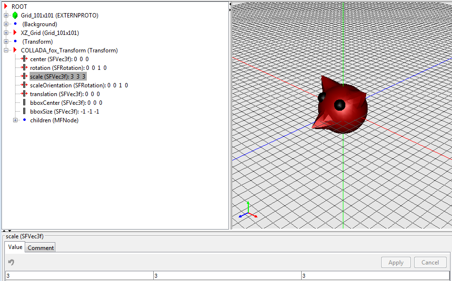
This example imports a Collada DAE file, fox.dae, into a scene with
predefined grid, gray background, and viewpoint. The fox head is a sphere with 1-m radius,
placed at the origin and looking in the direction of VRML +z-axis.
The fox.dae is shipped with the Simulink
3D Animation software. The path is
matlabroot/toolbox/sl3d/sl3ddemos/fox.dae.
From the MATLAB Toolstrip, in the Apps tab, in the Simulation Graphics and Reporting section, click 3D World Editor.
In the 3D World Editor, select File > New from Template.
In the file dialog box, select the
Gridsfolder and then select theXZGrid.x3dvirtual world file.Save the virtual world in the current folder. Select File > Save as and name the virtual world file
fox_dae.x3d.Import the DAE model. Select Nodes > Import From > COLLADA File. Select the
fox.daefile.Open the
COLLADA_fox_Transformnode and set thescalefield to 3 for each dimension.
Import a URDF File
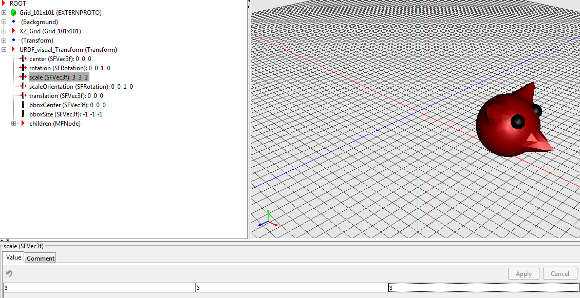
In this example, the fox.urdf file refers to
fox.dae file. The URDF file transforms the original DAE model so that
the fox is translated to the position [4 1 0] and rotated so that it points to the VRML
+x-axis direction.
The fox.urdf is shipped with the Simulink
3D Animation software.
From the MATLAB Toolstrip, in the Apps tab, in the Simulation Graphics and Reporting section, click 3D World Editor.
In the 3D World Editor, select File > New from Template.
In the file dialog box, select the
Gridsfolder and then select theXZGrid.x3dvirtual world file.Save the virtual world in the current folder. Select File > Save as and name the virtual world file
fox_urdf.x3d.Import the URDF model. Select Nodes > Import From > URDF File. Select the
fox.urdffile.Open the
URDF_visual_Transformnode and set thescalefield to 3 for each dimension.
Import an SDF File
SDF is an XML format that describes objects and environments for robot simulators,
visualization, and control, originally developed as part of the Gazebo robot simulator. The
folder in which the model.sdf file is located defines the SDF model name.
This example shows how to import a simple arm link mechanism.
The example assumes that you have
Download the
simple_armmodel folder (including all its contents) from this Gazebo model site: http://models.gazebosim.org/simple_arm/. To download all the folder contents, download and unpack themodel.tar.gzfile.From the MATLAB Toolstrip, in the Apps tab, in the Simulation Graphics and Reporting section, click 3D World Editor.
In the 3D World Editor, select File > New from Template.
In the file dialog box, select the
Gridsfolder and then select theXZGrid.x3dvirtual world file.Save the virtual world in the current folder. Select File > Save as and name the virtual world file
simple_arm.x3d.Import the SDF model. Select Nodes > Import From > SDF File. In the
simple_armfolder, select themodel.sdffile.Open the
SDF_simple_arm_Transformnode and set thescalefield to 3 for each dimension.
The import process creates in the model hierarchy some special
Transformnodes that make it easier to manipulate models. Each rotational joint in the SDF model is represented with aTransformnode with the name starting withaxis_. These nodes have rotation axes defined so that the model elements move consistently if you set the rotation angle to a different value.Change the rotation angle of a rotational joint node. For example, expand the
childrennode, then thejoint_arm_shoulder_pan_jointnode, then thechildren, and finally, theaxis_arm_shoulder_pan_joint. For therotationfield, set the fourth element to 1.
Tip
If you associate this virtual world with a VR Sink block in a Simulink model, you can use the VR Signal Expander block to set only the rotation angle (the fourth element of the rotation vector) of the
axis_xxxTransformnode rotation. Leave the first three elements of the vector unchanged. This approach preserves robot consistency with the way model authors defined movement of robot parts.
Define Viewpoint to Make Imported Model Visible
When you import a model, often it does not appear in the initial view of the virtual world. If necessary, create a viewpoint to make the imported model visible when the virtual world opens. If the imported model is not visible:
In the 3D World Editor, select the
ROOTnode.Select Nodes > Add > Bindable > Viewpoint.
To observe the imported model, navigate to a suitable location in the scene.
Populate viewpoint properties with current camera settings. In the tree hierarchy pane, right-click the viewpoint and select Copy values from current camera.
Save the virtual world.
Limitations
URDF import transforms robot hierarchy of links and joints into a VRML or X3D hierarchy of transforms. It imports only visualization properties from each link. Joints are represented by transforms that preserve rotation axes of the original revolute joints and axis alignment of prismatic joints.
SDF import transforms the hierarchy of SDF model objects into VRML or X3D hierarchy of
transforms the same way as URDF import. It supports a subset of SDF format objects and is
limited to visual objects under the Model element hierarchy. Supported
Geometry elements are geometric primitives and meshes.
