Virtual Reality Modeling Language (VRML)
Relationship of VRML and X3D
The X3D (Xtensible 3D) interface is the successor to the VRML (Virtual Reality Modeling Language) interface. The X3D interface supports VRML features. X3D also provides several extensions to VRML.
For details, see X3D Support.
VRML
You can use the Virtual Reality Modeling Language (VRML) to display three-dimensional objects in a VRML viewer. Simulink® 3D Animation™ supports VRML97.
VRML provides an open and flexible platform for creating interactive three-dimensional scenes (virtual worlds). Several VRML97-enabled browsers are available on several platforms. Also, you can choose from several VRML authoring tools. In addition, graphical software packages (CAD, visual art, and so on) offer VRML97 import/export features.
The Simulink 3D Animation product uses VRML97 technology for 3-D visualization.
VRML Support
The Virtual Reality Modeling Language (VRML) is an ISO standard that is open, text-based, and uses a WWW-oriented format. You use VRML to define a virtual world that you can display with a virtual world viewer and connect to a Simulink model.
The Simulink
3D Animation software uses many of the advanced features defined in the current VRML97
specification. The standard is ISO/IEC 14772-1:1997, available from http://www.web3d.org/documents/specifications/14772/V2.0/part1/javascript.html.
This format includes a description of 3-D scenes, sounds, internal actions, and WWW
anchors.
The software analyzes the structure of the virtual world, determines what signals are available, and makes them available from the MATLAB® and Simulink environment.
Simulink
3D Animation software ensures that the changes made to a virtual world are reflected in the
MATLAB and Simulink interfaces. If you change the viewpoint in your virtual world, this change
occurs in the vrworld object properties in MATLAB and Simulink interfaces.
The software includes functions for retrieving and changing virtual world properties.
Note
Some VRML worlds are automatically generated in VRML1.0. However, the Simulink 3D Animation product does not support VRML1.0. Save these worlds in the current standard for VRML, VRML97.
Other commercially available software programs can also perform the VRML1.0 to VRML97 conversion.
VRML Compatibility
The Simulink 3D Animation product currently supports most features of VRML97, with the following limitations:
The Simulink 3D Animation server ignores the VRML
Scriptnode, but it passes the node to the VRML Viewer. Passing the node allows you to run VRML scripts on the viewer side. You cannot run them on the Simulink 3D Animation server.In keeping with the VRML97 specification, the Simulink 3D Animation Viewer ignores BMP files. As a result, VRML scene textures sometimes display improperly in the Simulink 3D Animation Viewer. To display scene textures properly, replace all BMP texture files in a VRML scene with PNG, JPG, or GIF equivalents.
For a complete list of VRML97 nodes, refer to the VRML97 specification.
Virtual World Coordinate System
Take coordinate systems into account when you want to:
Display a virtual world object in a particular position.
Move a virtual world.
Export non VRML models from CAD tools (including CATIA) and robot visual representations (URDF files) to use with Simulink 3D Animation.
Have a virtual world interact with MATLAB or Simulink.

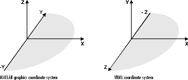
The VRML coordinate system is different from the MATLAB and Aerospace Blockset™ coordinate systems. VRML uses the world coordinate system: the y-axis points upward and the z-axis places objects nearer or farther from the front of the screen. The larger the z-axis value, the closer the object appears to the viewer. Understanding the coordinate system is important when you interact with different coordinate systems. Simscape™ Multibody™ uses the same coordinate system as VRML.
Here are some key VRML coordinate system concepts:
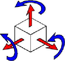
Rotation angles — In VRML, rotation angles are defined using the right-hand rule. Imagine your right hand holding an axis while your thumb points in the direction of the axis toward its positive end. Your four remaining fingers point in a counterclockwise direction. This counterclockwise direction is the positive rotation angle of an object moving around that axis.

Child objects — In the hierarchical structure of a VRML file, specify the position and orientation of child objects relative to the parent object. The parent object has its local coordinate space defined by its own position and orientation. Moving the parent object also moves the child objects relative to the parent object.
Measurement units — All lengths and distances are measured in meters, and all angles are measured in radians.
Simulink
3D Animation provides a set of functions that can help you convert between different
representations of orientation in space. An example of a coordinate conversion function is
vrrotmat2vec, which converts a rotation from a matrix to an axis-angle
representation.
VRML File Format
You need not have any substantial knowledge of the VRML format to use the VRML authoring tools to create virtual worlds. However, a basic knowledge of VRML scene description helps you create virtual worlds more effectively. A basic knowledge also gives you a good understanding of how you can control the virtual world elements using Simulink 3D Animation software.
For more information, see the VRML97 Reference at https://www.web3d.org. Many
specialized VRML books can help you understand VRML concepts and create your own virtual
worlds. For more information about the VRML, refer to an appropriate third-party VRML book.
VRML uses a hierarchical tree structure of objects (nodes) to describe a 3-D scene. Every node in the tree represents some functionality of the scene. There are many different types of nodes. Some of them are shape nodes (representing real 3-D objects), and some of them are grouping nodes used for holding child nodes. Here are some example nodes:
Box— Represents a box in a scene.Transform— Defines position, scale, scale orientation, rotation, translation, and children of its subtree (grouping node).Material— Corresponds to material in a scene.DirectionalLight— Represents lighting in a scene.Fog— Allows you to modify the environment optical properties.ProximitySensor— Brings interactivity to VRML97. This node generates events when you enter, exit, and move within the defined region in space.
Each node contains a list of fields that hold values defining parameters for its function.
Nodes can be placed in the top level of a tree or as children of other nodes in the tree hierarchy. When you change a value in the field of a certain node, all nodes in its subtree are affected. This feature allows you to define relative positions inside complicated compound objects.
You can mark every node with a specific name by using the keyword DEF in the VRML scene
code. For example, the statement DEF MyNodeName Box sets the name for
this box node to MyNodeName. You can access the fields of only those
nodes that you name in a virtual world.
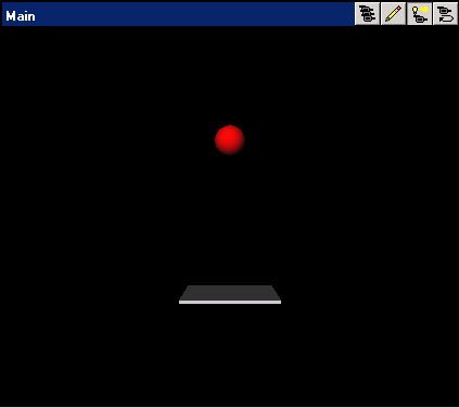
In the following example of a simple VRML file, two graphical objects are modeled in a 3-D scene. A flat box with a red ball above it represents the floor. The VRML file is a readable text file that you can write in any text editor.
#VRML V2.0 utf8
# This is a comment line
WorldInfo {
  title "Bouncing Ball"
}
Viewpoint {
  position 0 5 30
  description		"Side View"
}
DEF Floor Box {
  size 6 0.2 6
}
DEF Ball Transform {
  translation		 0 10 0
  children Shape {
    appearance Appearance {
      material Material {
        diffuseColor 1 0 0
      }
    }
    geometry Sphere {
    }
  }
}
The first line is the VRML header line. Every VRML file must start with this header line. It indicates that the file is a VRML 2 file and that the text objects in the file are encoded according to the UTF8 standard. You use the number sign (#) to comment VRML worlds. A VRML viewer ignores everything on a line after the # sign is ignored, except for the first header line.
Most of the box properties are left at their default values – distance from the center
of the coordinate system, material, color, and so on. Only the name Floor
and the dimensions are assigned to the box. To be able to control the position and other
properties of the ball, it is defined as a child node of a Transform type node. Here, the
default unit sphere is assigned a red color and a position 10 m above the floor. In
addition, the virtual world title is used by VRML viewers to distinguish between virtual
worlds. A suitable initial viewpoint is defined in the virtual world VRML file.
When displayed in a VRML viewer, you see the floor and red ball.

