Identify and Fix Common Linearization Issues
When you linearize a Simulink® model, if your linearization results are not as expected, you can identify common linearization issues using the Linearization Advisor. The Linearization Advisor collects diagnostic information regarding individual block linearizations. Using this information, you can:
View linearization details and operating points for each linearized block in your model.
Identify potentially problematic blocks that cause common linearization issues.
Determine which blocks are on and off the linearization path and which blocks contribute to the model linearization result.
Search linearization results for blocks that meet specified criteria.
Enable Linearization Advisor
Since collecting diagnostic information adds linearization overhead, the Linearization Advisor is disabled by default. To collect diagnostic information, you must enable the Linearization Advisor before you linearize your model.
To enable the Linearization Advisor, in the Model Linearizer, on the Linear Analysis tab, select Linearization Advisor.

When you select this option and linearize your model, the software opens an Advisor tab for troubleshooting your linearization results.
Tip
To make viewing the diagnostic information easier, you can minimize the data browser.
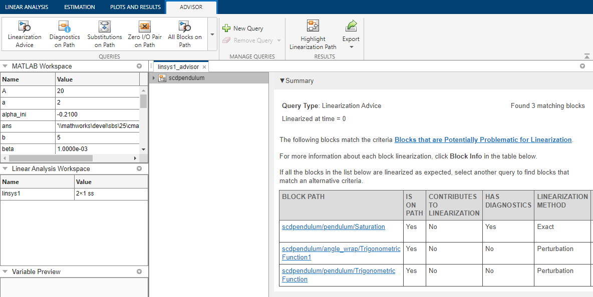
On the Advisor tab, you can gain insight into your model linearization by querying the diagnostic information. To do so, use the built-in queries in the Queries section, or create custom queries in the Manage Queries section.
When you run a query, the navigation tree lists the linearized blocks in your model that match the query search criteria. The tree structure reflects the model hierarchy.
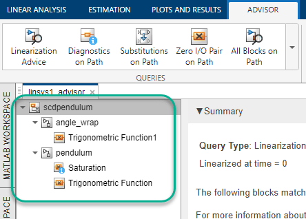
To view a table of all blocks that match the search criteria, in the navigation tree, click the top-level model name. You can also view all blocks in a subsystem that satisfy the query by clicking the subsystem name. Each entry in the table summarizes the linearization diagnostics for a single block.

To view detailed diagnostic information for a block in a table, in the corresponding row, click Block Info. You can troubleshoot the block linearization using the detailed diagnostic information. For more information, see Block Linearization Troubleshooting.
For an example of interactive troubleshooting using the Linearization Advisor, see Troubleshoot Linearization Results in Model Linearizer.
Tip
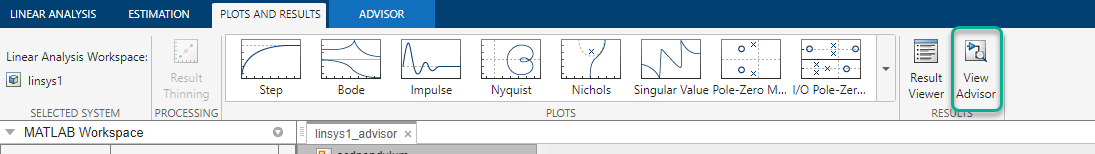
If you close the Advisor tab for a given linearization, you can reopen it from the Plots and Results tab.
In the Linear Analysis Workspace, select the linearized model you want to troubleshoot. Then, click View Advisor. This option is only available if you enabled the Linearization Advisor before linearizing the model.
You can also create a LinearizationAdvisor object when you linearize models at the command
line. You can then troubleshoot the linearization results using the advise and find functions. For an example, see Troubleshoot Linearization Results at Command Line.
Blocks That Are Potentially Problematic for Linearization
As a starting point for troubleshooting, the Linearization Advisor searches the linearization diagnostic information for blocks that can cause common linearization issues. These potentially problematic blocks are on the linearization path and satisfy at least one of the following criteria.
| Criteria | Description |
|---|---|
| Blocks with linearization diagnostic messages | Diagnostic messages indicate blocks with configurations or linearizations that correspond to common linearization problems. |
| Blocks that linearize to zero | Blocks with zero linearizations do not contribute to the linearization result and can remove other blocks from the linearization result. |
| Blocks with substituted linearizations | Errors in defining substitute linearizations can be difficult to diagnose. |
For more information on the linearization path, see Linearization Path.
In the Model Linearizer, the diagnostic information for these blocks is listed on the Advisor tab when the tab first opens. Also, to access this diagnostic information at any time, in the Queries section, click Linearization Advice.

You can troubleshoot the linearizations of these blocks using the Linearization Advisor. For more information on troubleshooting block linearizations using diagnostic information, see Block Linearization Troubleshooting.
At the command line, the advise function returns diagnostic
information for these blocks.
Blocks with Linearization Diagnostic Messages
Linearization diagnostic messages indicate blocks with properties or linearizations that correspond to common linearization problems. Fixing linearization issues identified in diagnostic messages is a good first step when troubleshooting your linearization.
Some block configurations that can generate diagnostic messages include:
Blocks with non-floating-point input or output signals and no predefined exact linearization. Such blocks linearize to zero and generate diagnostic messages.
Discontinuous blocks linearized at an operating point near a discontinuity. If such blocks are not treated as a gain during linearization, the software can generate diagnostic messages regarding their linearization.
Blocks with least one input/output pair that linearizes to zero which causes a zero input/output pair in the overall model linearization.
Blocks that do not support linearization because they do not have a predefined exact linearization and do not support numerical perturbation.
Some diagnostic messages propose solutions to their corresponding linearization issues. For example, when an input signal is outside the saturation limits of a Saturation block, the diagnostic message proposes treating the block as a gain during linearization.
Blocks That Linearize to Zero
A common cause of linearization issues is a block that unexpectedly linearizes to a gain of zero. To diagnose the cause of a zero block linearization, you can consider:
Any corresponding diagnostic messages. These messages can highlight common causes of zero linearizations and propose potential solutions.
The block operating point; that is the values of the block states and inputs at the model operating point used for linearization. For example, if the input to a saturation block is outside the block saturation limits, and the block is not configured to linearize as a gain, the block linearizes to zero.
The block parameters. For example, if a block is configured to use non-floating-point inputs or states and is linearized using numerical perturbation, it linearizes to zero.
A zero block linearization does not necessarily indicate a linearization
problem; that is, you may expect a block to linearize to zero under the expected
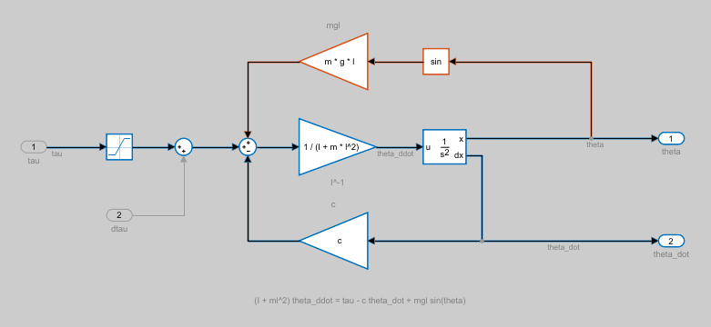
operating conditions of the model. For example, if a Trigonometric
Fcn block is configured as a sin function and the
input value is π/2 at the model operating point, then the block linearizes to
zero.
Blocks with Substituted Linearizations
Errors in defining a custom block linearization can be difficult to diagnose. After fixing issues related to diagnostic messages and zero linearizations, if your model still does not linearize as expected, verify that any substituted block linearizations in your model are correct.
For more information on specifying substitute block linearizations, see Specify Individual Block Linearization.
Find Specific Blocks in Linearization Results
If your model still does not linearize as you expect after fixing linearization issues related to potentially problematic blocks, you can query the Linearization Advisor for additional block diagnostic information. You can gain insight into your model linearization using this information. For example, you can investigate:
Blocks that are linearized using numerical perturbation.
Sampling rates of block linearizations in multirate models by finding blocks with a specified sample time.
Blocks that have delays that can cause linearization issues.
Blocks that are not on the linearization path.
For more information, see Find Blocks in Linearization Results Matching Specific Criteria.
Linearization Path
The linearization path is the graphical connection in the Simulink model from the linearization inputs to the linearization outputs. A block is on the linearization path if at least one linearization input is connected to at least one linearization output through that block. For more information on specifying linearization inputs and outputs, see Specify Portion of Model to Linearize.
When a block is on the linearization path, its linearization can contribute to the overall model linearization. Blocks that linearize to zero do not contribute to the model linearization and can prevent branches of the linearization path from contributing to the model linearization.
Blocks that are not on the linearization path can still affect the linearization of other blocks, and therefore the model linearization, by modifying the operating points or parameters of the other blocks. For example, consider the following Product block that is on the linearization path (highlighted in blue):
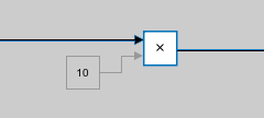
The constant block is not on the linearization path. However, the value of the constant affects the operating point of the Product block, which in turn affects the linearization from the first input of the Product block to the output.
Highlight Linearization Path
To visualize the linearization path and view blocks that contribute to the model linearization, you can highlight the linearization path in the Simulink model using the Linearization Advisor. A block is on the linearization path if there is a signal path from at least one linearization input to at least one linearization output that passes through the block.
After you linearize your model with the Linearization Advisor enabled, to highlight the linearization path, in the Model Linearizer, on the Advisor tab, click Highlight Linearization Path.

The software highlights the linearization path in the model, showing which blocks are on the path and which blocks contribute to the model linearization. Blocks highlighted in:
Blue are on the linearization path and numerically influence the model linearization.
Red are on the linearization path, but have no influence on the model linearization due to at least one block on the linearization path that is linearized to zero.
Gray are not on the linearization path and do not contribute to the model linearization.

To turn off the highlighting, close the Linearization path dialog box.
You can also highlight the linearization path from the command line using the
highlight function.
Troubleshoot Batch Linearizations
If you linearize your model at multiple operating points, you can troubleshoot each resulting linear model using Linearization Advisor.
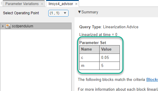
After batch linearizing the model, on the Advisor tab, in the Select Operating Point drop-down list, select the operating point for which you want to troubleshoot the linearization.
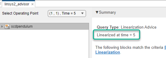
If you batch linearized your model using:
Parameter variation, the linearization summary shows the parameter values that correspond to the selected operating point.
Multiple simulation snapshot times, the linearization summary shows the time at which the model was linearized.
Multiple trimmed operating points, the linearization summary does not show additional information about the operating point. To view details about the operating points, on the Linear Analysis tab, in the Operating Point drop-down list, select the operating point array used for linearization. In the same drop-down list, select
Edit.Then, in the Edit dialog box, in the Select Operating Point drop-down list, select an operating point. The location of the operating point in this drop-down list corresponds to the location in the drop-down list on the Advisor tab.