PRBS Input Signals
A pseudorandom binary sequence (PRBS) is a periodic, deterministic signal with white-noise-like properties that shifts between two values. A PRBS signal is inherently periodic with a maximum period length of 2n–1, where n is the PRBS order.
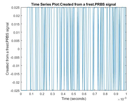
You can use a PRBS input signal for frequency-response estimation at the command line or in Model Linearizer. The estimation algorithm injects the PRBS signal at the input analysis point you specify for estimation, and measures the response at the output analysis point. PRBS signals are useful for estimating frequency responses for communications and power electronics applications.
Using PRBS input signals, you can:
Reduce total estimation time compared to using sinestream input signals, while producing comparable estimation results.
Obtain faster frequency response estimation with a higher frequency resolution than using chirp input signals.
When you create your PRBS input signal, specify the following parameters.
Signal amplitude — The peak-to-peak range of the signal.
Sample time — Set the sample time to match the sample time at the signals that correspond to the input and output linear analysis points.
Signal order — The maximum length of the PRBS signal is 2n–1, where n is the signal order.
Number of periods — Number of periods Np in the PRBS signal.
When specifying your PRBS signal parameters, consider the following:
Set the amplitude such that the system is properly excited for your application. If the input amplitude is too large, the signal can deviate too far from the model operating point. If the input amplitude is too small, the PRBS signal is indistinguishable from noise and ripples in your model.
For a given sample time, to increase the resolution over the low-frequency range, increase the order of the PRBS signal.
For most frequency response estimation applications, use a single period. Doing so produces a flat frequency response across the frequency range of the signal.
The frequency range of the generated PRBS signal is [Fmin,Fmax], where and . FN is the Nyquist frequency of the signal.
You can also create a PRBS signal with parameters based on the dynamics of a linear
system, sys. For instance, if you have an exact linearization of your
system, you can use it to initialize the parameters.
When you set the PRBS parameters using a linear system, the amplitude of the signal is
0.05 and the number of periods is 1. To set the sample
time and order of the signal, the software first selects a signal frequency range,
[Fmin,Fmax],
based on the dynamics of sys.
If sys is a discrete-time system, then:
The sample time of the PRBS is equal to the sample time of
sys.The order of the PRBS is as follows, where
⌈.⌉is the ceiling operator.
If sys is a continuous-time system, then:
The sample time of the PRBS is
The order of the PRBS is as follows, where
⌊.⌋is the floor operator.
Create PRBS Signals Using Model Linearizer
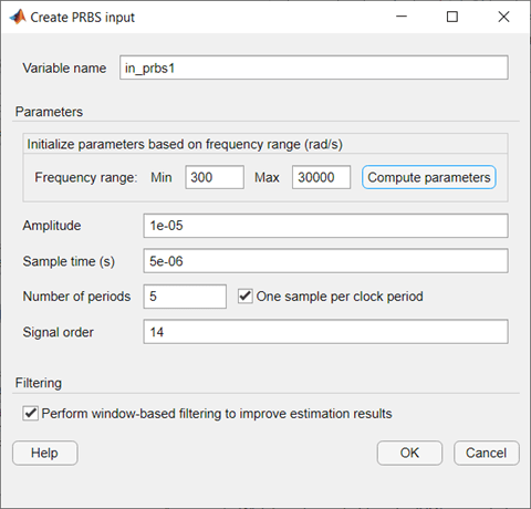
In the Model Linearizer, to use a PRBS input signal for estimation, on the Estimation tab, select Input Signal > PRBS Pseudorandom Binary Sequence.
In the Create PRBS input dialog box, specify the name of the PRBS signal object in Variable Name. You can then specify the parameters of your PRBS input signal using the following fields.
Amplitude — Signal amplitude
Sample time — Sample time
Number of periods — Number of periods
Signal order — Signal order
You can also automatically determine the parameters Number of periods and Signal order based on a frequency range of interest. Automatic parameter determination helps create an input signal that leads to an accurate frequency response over a specified frequency range.
To determine the parameters automatically, first set the Sample time parameter to match the sample time at the point of signal injection. Next, specify the frequency range of interest in rad/s using the Min and Max parameters, and then click Compute parameters.
Additionally, you can:
Use the One sample per clock period parameter to specify whether the signal remains constant for one sample per clock period or multiple samples per clock period. Use this parameter if you have Number of periods > 1. By default, this option is enabled and the generated signal is constant over one sample. When you disable this option, the generated signal is constant for the specified number of samples.
Use the Perform window-based filtering to improve estimation results parameter to apply Hann window-based filtering, which produces a smoother frequency response estimation result.
Create PRBS Signals Using MATLAB Code
To create a PRBS signal for estimation at the command line with
frestimate, use a frest.PRBS
object.
Create PRBS Signals in Simulink
Since R2024a
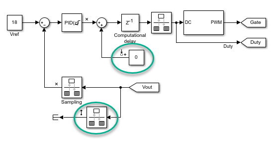
To create a PRBS signal for estimation in Simulink®, use the PRBS Signal Generator block. This block is helpful when you to generate perturbation signals to inject in your plant models in desktop simulation or on hardware through code generation. You can then collect the plant response data to the perturbation signal and perform custom processing to identify plant characteristics.
Improve Frequency Response Result at Low Frequencies
To improve the frequency response estimation result at low frequencies, you can use a different sample time other than the sample time in the original model. To do so, modify your model to use a Constant block at the input analysis point and a Rate Transition block at the output analysis point.
For both the Constant block and the Rate Transition block, specify a new sample time for your PRBS signal that is larger than the original sample time of the model.
The ability to change the sample time of the PRBS input signal provides an additional degree of freedom in the frequency response estimation process. By using a larger sample time than in the original model, you can obtain a higher resolution frequency response estimation result over the low-frequency range. Additionally, running estimation at lower sampling rate reduces processing requirements when deploying to hardware.