主要内容

watertank Simulink 模型

R2026b

Simulink® 模型 watertank 包括一个单环反馈系统中的非线性 Water-Tank System 被控对象和 PI 控制器。

Simulink block diagram of the watertank model. A Desired Water Level constant block with value 10 provides the reference input to a summing junction, which computes the error by subtracting the feedback. The error passes through a PID Controller block, which drives the Water-Tank System block. The system output feeds back to the summing junction and also connects to a Scope block.

Water-Tank System 如下图所示。

Simulink block diagram of the Water-Tank System subsystem. The input voltage V passes through a b/A gain block into a summing junction. The output of the summing junction integrates through an integrator block to produce the water height H at the output. A negative feedback path takes H through a square root, then multiplies by the gain a/A, and feeds back into the summing junction.

水从顶部进入水箱,其速率与施加于泵上的电压 V 成正比。水通过水箱底部的开口流出,其速率与水箱中的水位 H 的平方根成正比。水流速率中存在平方根,这导致生成一个非线性被控对象。
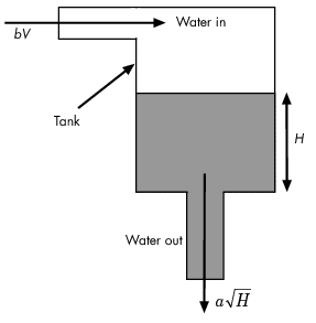
Schematic diagram of the water tank system. Water enters the tank from the top at a rate of bV, where V is the voltage applied to the pump. The tank is shown as a rectangular vessel with water height H. Water exits through an opening at the base of the tank at a rate of a times the square root of H.

下表描述 Water-Tank System 的变量、参数、微分方程、状态、输入和输出。

变量

H 是水箱中的水位。

Vol 是水箱中水的体积。

V 是施加于泵上的电压。

参数

A 是水箱的横截面积。

b 是与流入水箱的水流速率相关的常量。

a 是与流出水箱的水流速率相关的常量。

微分方程

ddtVol=AdHdt=bV−aH

状态H
输入V
输出H