Airframe Controller Tuning
This example shows how to design two feedback loops in a cascaded control system to track reference signals. The design uses the body rate (q) as an inner feedback loop and the acceleration (az) as an outer feedback signal. This example is based on the Simulink® Control Design™ example Cascaded Multiloop Feedback Design (Simulink Control Design).
After loading the model and pre-configured Control System Designer app session, you can design a new controller using Response Optimization.
Requires Simulink® Control Design™.
Opening the Model
Open the model using the following command, and double click on the orange block to launch the Control System Designer.
open_system('airframe_demo')
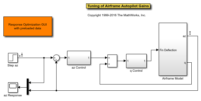
Design Overview
The goal of the design is to have an overall rise time of under 0.5 seconds for the outer feedback loop. A preliminary design is done using Simulink Control Design (see Cascaded Multiloop Feedback Design (Simulink Control Design).) and is used as a starting point for optimization. The controller must satisfy the following requirements:
A Gain Margin >= 10db and Phase Margin >= 50 degrees for the inner feedback loop.
A Gain Margin >= 10db and Phase Margin >= 60 degrees for the outer feedback loop.
An overshoot of at most 1%, a 80% rise time of 0.5 seconds, and a 99% rise time of 0.6 seconds for the step response of the outer loop.
These design requirements have been added to the Control System Designer app. To complete the design using response optimization, in the Control System tab, in the Tuning Methods drop-down list, select Optimization Based Tuning. In the Response Optimization window, click Start Optimization.
bdclose('airframe_demo')