Redesigned Simulink Test Manager User Interface (Tech Preview)
R2026bNote
The redesigned Simulink® Test Manager is a tech preview in R2026b. The primary purpose of the tech preview is to provide early access to the most common testing workflows. For more information about supported workflows, see Overview of the Redesigned Simulink Test Manager (Tech Preview).
To enable the feature, click the New Test Manager button in the
existing Test Manager or use the sltest.stmv2.open function at
the command line.
The redesigned Simulink Test Manager has new toolstrip sections and buttons, a new Test Files pane, and new tabs that correspond to items in the Test Files pane.
For information about changed features, see Import Tests.
For information about features that are not supported in the tech preview, see Limitations of the Tech Preview.
New Toolstrip Sections and Buttons
In addition to toolstrip sections and buttons in the previous version of the Test Manager, the redesigned version includes new toolstrip sections and buttons.
Add Component Under Test button — Adds a new CUT to the test file.
Add Test Case button — Adds a new test case to the CUT .
Test Interface section — Lists items that you can add to the CUT. To enable this section, highlight a CUT in the Test Pane to open its CUT tab.
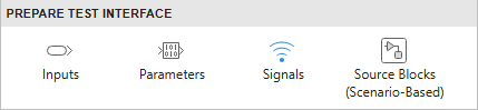
Check Test Interface button — Verifies that the signals added in Test Interface section of the CUT tab are valid.
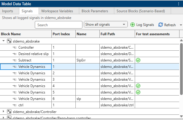
Model Data Table button — Opens the Model Data Table pane. You can use this pane to view and edit model data of the CUT. The pane includes inports,signals, workspace variables, block parameters, and source blocks, each in a separate tab. You can use this pane as an alternative way to set up the CUT.
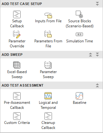
Prepare Test Case section — Lists items you can add to the test case. To enable these buttons, select a test case from the Test Files pane. For information about each item, see
Use Parallel button — Enables using Parallel Toolbox when running tests.
Results button — Opens the Test Results app. Use this app to view and compare test results.
Import button — Imports an MLDATX test file or a project into files in the redesigned Test Manager.
Add Setup Callback button — Adds a callback that runs before all test cases in a runlist.
Add Cleanup Callback button — Adds a callback that runs after all test cases in a runlist.
Add Comparison button — Adds a comparison section to the run settings tab. You use the comparison section to compare two run settings and set tolerances.
Test Files Pane
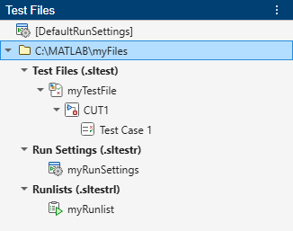
The Test Files pane lists the folder that contains the test file and the Test Files (.sltest), Run Settings (.sltestr), and Runlists (.sltestrl) sections. When you click a test file, CUT, test case, run settings, or runlist item, its tab opens.
Test File Tab
Select a test file in the Test Files pane to open its test file tab. Use this tab to specify the model to test.
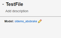
Click the Select model button  to add the model.
CUT Tab
Select a CUT in the Test Files pane to open its CUT tab. This tab contains the Component Under Test, Test Interface, and Advanced Settings sections. When you open a CUT tab, the Workspace pane opens. Use this panel to add variables to use in tests and view reserved variables and aliases that you create in the CUT tab.
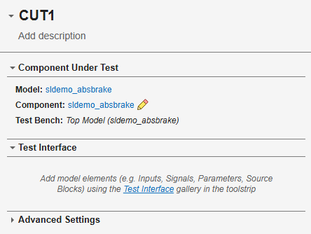
The Component Under Test section contains these parameters:
Model — Model to test. You can click the model name to open the model.
Component — Component to test. By default, the whole model is the component to test. To select the component to test and the test bench, click the Update component under test button
to open the Select Component Under Test dialog
box.Test Bench — Test bench to use. By default, the top model is the test bench. To change the test bench, click the Update component under test button
next to Component. The test
bench options depend on the type of component you select. These options can include:Top Model— Use the top model as the test bench.Referenced Model— Use the selected referenced model in the Component list as the test bench.Managed Automatically— Let the software create and manage the test bench. The software automatically updates the test bench when the model changes. Click the Check compatibility button to check whether the software can
automatically manage the selected component as the test bench. If the
component is compatible, the software creates and opens a test harness to
use as the test bench. The harness name is
to check whether the software can
automatically manage the selected component as the test bench. If the
component is compatible, the software creates and opens a test harness to
use as the test bench. The harness name is
<model>_AutoHarness.Test Harness— Use an internal or external test harness as the test bench. You can enter the name of an existing harness or create a test harness by clicking the Create new test harness button . For more information, see Create Test Harness Dialog Box Properties.
The Test Interface section contains the inputs, parameters, signals, and source blocks for the CUT. To add elements in this section, use the buttons in the Test Interface section of the toolstrip.
In the Inputs, Parameters, and
Signals sections, you can add items from the model by clicking Add
from model or by using the Model Data Table
pane. For source blocks, you must use the Model Data Table pane.
In the Advanced Settings section, you can select whether to use fast restart when testing the CUT.
Test Case Tab
Select a test case in the Test Files pane to open its test case tab. Use this tab to add setup and assessment items. You can also add sweep tests. When you open a test case tab, the Workspace pane opens. Use this pane to add variables to tests and view reserved variables and aliases.
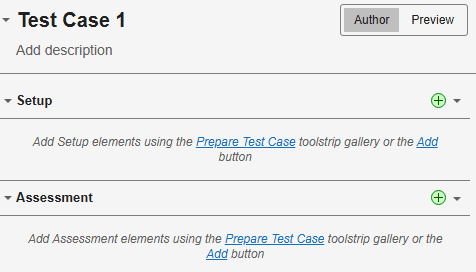
The Prepare Test Case gallery in the toolstrip contains items that you can add to the test case tab.
Add Test Setup
The Add Test Case section of the gallery contains Setup Callback, Inputs From File, Source Blocks (Scenario-Based), Parameter Override, Parameters From File, and Simulation Time buttons.
The
In the Setup Callback section, you can define a callback that runs at the beginning of this test case.
In the File-based Inputs section, you can specify the file
from which to use inputs for the test. Click the Choose file  or Generate template
  . To map the file data to the CUT elements. click the
Configure mapping button
. To map the file data to the CUT elements. click the
Configure mapping button  .To view the contents of the inputs file, click
Preview at the top of the test case tab.
.To view the contents of the inputs file, click
Preview at the top of the test case tab.
In the Source Blocks (Scenario-Based) section, scenario-based source blocks from the model. Click the Refresh button to Source blocks that are available in the tech preview are the Test Sequence and Signal Editor blocks.
In the Simulation Time section, you can specify the simulation Start Time and Stop Time in seconds.
In the Parameter Override section, click the Add
from model button . Then in the model, select the block parameters you
want to override. Click the Done button in the dialog box, and
then enter the Override Values in the table. You cannot have both a
Parameter Override section and a Parameters from
File section in the test case.
In the Parameters From File section, specify the parameter override file to use. You cannot have both a Parameter Override section and a Parameters from File section in the test case.
Add Sweep
The Add Sweep section of the gallery contains Excel-Based Sweep and Parameter Sweep buttons.
In the Excel-Based Sweep section, you can specify an Excel file of values to sweep. You can view the raw data, which shows the data as it appears in the Excel file, or view it as processed data, which shows the formatted data.
In the Parameter Sweep section, you can add parameters and range of parameter values to sweep. The Range Expression must be a valid MATLAB expression. If you specify a parameter override in the Setup section of the test case tab and sweep the same parameter, the sweep value takes precedence.
The Exhaustive and Sequential options apply when there is more than one parameter to sweep. Sequential sweeps must have parameters with an equal number of range values. The first value from each parameter range forms the first sweep, the second value from each forms the second sweep, and so on. For exhaustive sweeps, the first value of the first parameter sweeps with every value of the second parameter, then the second value of the first parameter sweeps with all the second parameter values, and so on. If there are more than two parameters, the sweeps cover all combinations of parameters.
Add Test Assessment
The Add Test Assessment section of the gallery contains Pre-Assessment Callback, Baseline, Custom Criteria, Logical and Temporal, and Cleanup Callback buttons.
In the Pre-Assessment Callback section , you can specify a callback that runs before the assessments for this test case.
In the Baseline section, you can click specify a file of
baseline values to compare to the test case output. Click the Choose file
or Capture button. To view the contents of the baseline file,
click Preview at the top of the test case tab.
In the Custom Criteria section, you can create a test assessment using a script or MATLAB expression
In the Logical and Temporal section, you can add a bounds
check, custom, or trigger-response assessment of the test case. Click the Add
Assessment button  and select the assessment type. You can use aliases,
reserved variables, and local variables in the test case assessment definitions.
and select the assessment type. You can use aliases,
reserved variables, and local variables in the test case assessment definitions.
In the Cleanup Callback section, you can specify a callback that runs after the assessments for this test case.
Run Settings Tab
Select a run settings item in the Test Files pane to open its run settings tab.
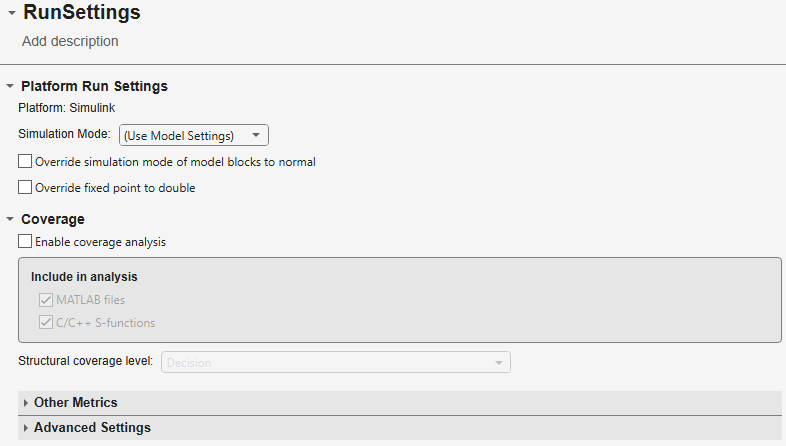
The Platform Run Settings section contains these parameters:
Platform — Only Simulink is available as a platform in the tech preview.
Simulation Mode — Specifies the Simulink simulation mode:
Use Model Settings,Normal,Accelerator,Rapid Accelerator,SIL, andPIL.Override simulation mode of model blocks to normal — Select to use normal simulation mode for all model blocks.
Override fixed point to double — Use
doubledata type.
The Coverage section contains these parameters:
Enable coverage analysis — Turn on coverage collection
Include in analysis — Include coverage collection for MATLAB files and C/C++ S-functions in addition to other model coverage
Structural coverage level — Type of coverage to collect. See the description of each level in Types of Model Coverage (Simulink Coverage).
—
The Other Metrics section contains coverage metrics options See the description of each metric in Types of Model Coverage (Simulink Coverage).
The Advanced Settings section contains these advanced coverage parameters:
Force block reduction off — Select to analyze coverage for every supported block in the model.
Treat Simulink Logic blocks as short-circuited — Select to have coverage consider the order of operands in blocks that perform a logical operation. For more information, see the Treat Simulink logic blocks as short-circuited (Simulink Coverage) parameter.
MCDC Mode — Specify the definition of MCDC to use during coverage analysis. For more information, see Modified Condition and Decision Coverage (MCDC) Definitions in Simulink Coverage (Simulink Coverage).
Runlist Tab
Select a runlist item from the Test Files pane to open the associated runlist tab.
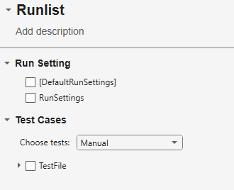
The runlist tab includes these parameters:
Run Setting section— Select the run setting or settings to use. If you select more than one run setting, each selected test case runs for each run setting. To run a back-to-back test, you specify one simulation mode for one run settings file and a different simulation mode for another run settings file.
To compare two run settings, click Add Comparison in the toolstrip and select the run settings in the Comparisons section, and optionally specify the tolerances. You can add multiple Comparisons sections. Each test case runs for each run setting.
Test Cases section — Select
ManualorBy queryfrom Choose tests. If you selectManual, the section shows a hierarchy of test files from which you select the items to run. If you selectBy query, you specify which tests to run by specifying the conditions to include or exclude.
To see a list of the test cases set up to run, click Preview at the top of the runlist tab.

