Rack and Pinion Constraint
Kinematic constraint between a translating rack body and a rotating pinion body

Libraries:
Simscape /
Multibody /
Gears and Couplings /
Gears
Description
The Rack and Pinion Constraint block represents a kinematic constraint between a translating rack body and a rotating pinion body. The base frame port identifies the connection frame on the pinion body and the follower frame port identifies the connection frame on the rack body. The pinion rotation axis and the rack translation axis coincide with the frame z-axes.
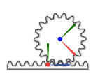
The block represents only the kinematic constraint characteristic to a rack-and-pinion system. Gear inertia and geometry are solid properties that you must specify using solid blocks. The gear constraint model is ideal. Backlash and gear losses due to Coulomb and viscous friction between teeth are ignored. You can, however, model viscous friction at joints by specifying damping coefficients in the joint blocks.
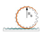
Gear Geometry
The rack-and-pinion constraint is parameterized in terms of the dimensions of the
pinion pitch circle. The pitch circle is an imaginary circle concentric with the
pinion body and tangent to the tooth contact point. The pitch radius, labeled
RB in the figure, is the radius
that the pinion would have if it was reduced to a friction cylinder in contact with
a brick approximation of the rack.
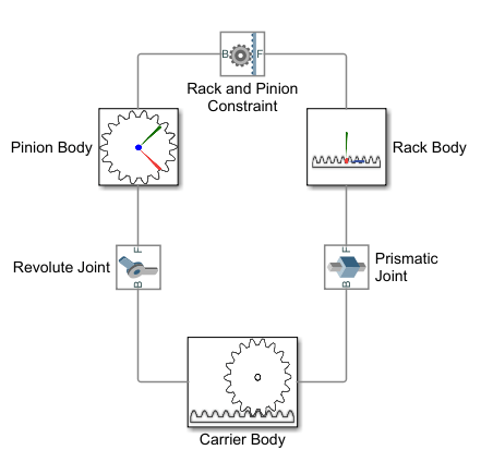
Gear Assembly
Gear constraints occur in closed kinematic loops. The figure shows the closed-loop topology of a simple rack-and-pinion model. Joint blocks connect the rack and pinion bodies to a common fixture or carrier, defining the maximum degrees of freedom between them. A Rack and Pinion Constraint block connects the rack and pinion bodies.
Assembly Requirements
The block imposes special restrictions on the relative positions and orientations of the gear connection frames. The restrictions ensure that the gears assemble only at distances and angles suitable for meshing. The block enforces the restrictions during model assembly, when it first attempts to place the gears in mesh, but relies on the remainder of the model to keep the gears in mesh during simulation.
Position Restrictions
The distance between the base and follower frame origins along the follower frame y-axis must equal the pinion radius. This constraint ensures that the pitch point of the rack is at the proper distance from the rotation axis of the pinion.
The follower frame origin must lie on the xy plane of the base frame. This constraint ensures that the pitch point of the rack is coplanar with the pitch circle of the pinion.
Orientation Restrictions
The x-axis of the follower frame must be perpendicular to the xy plane of the base frame. This constraint ensures that the rack and pinion are coplanar, and therefore that their motion axes are perpendicular to each other.
Examples
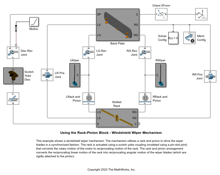
Using the Rack-Pinion Block - Windshield Wiper Mechanism
A windshield wiper mechanism. The mechanism utilizes a rack and pinion to drive the wiper blades in a synchronized fashion. The rack is actuated using a scotch yoke coupling (modeled using a pin-slot joint) that converts the rotary motion of the motor to reciprocating motion of the rack. The rack and pinion arrangement converts the reciprocating linear motion of the rack into reciprocating angular motion of the wiper blades (which are rigidly attached to the pinion).
Ports
Frame
Output
Parameters
Extended Capabilities
Version History
Introduced in R2013a