Creating Custom Solid Frames
Solid Frames
By default, the Solid block provides only a reference frame port, labeled R. In simple shapes, such as Brick Solid, Spherical Solid, and Cylindrical Solid, the reference frame origin coincides with the solid center of mass. The same is generally not true of the more sophisticated Extruded Solid and Revolved Solid shapes, nor is it of imported solid shapes.
Reference Frame of a Solid
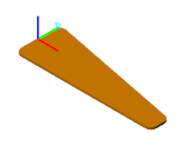
In many applications, the reference frame of a solid is inadequate for connecting joints and constraints or for applying forces and torques. In such cases, you can create new frames external to the Solid block using the Rigid Transform block. This block enables you to define the new frame by specifying translation and rotation transforms numerically.
An alternative approach, and one that is often more intuitive, is to create new frames directly in the Solid block dialog box using the frame-creation interface. This interface enables you to define new frames interactively by aligning the frame origin and axes with geometric features such as planes, lines, and points.
Reference and Custom Frames of a Solid
Opening the Frame-Creation Interface
The frame-creation interface is accessible through the Solid block dialog box. To open the interface, in the Frames expandable area, select the Create button ![]() . If you change any of the block parameters, you must first update the solid visualization by selecting the Update Visualization button
. If you change any of the block parameters, you must first update the solid visualization by selecting the Update Visualization button ![]() .
.
Geometry-Based Frame Placement
You can define frames based on geometric features of the solid or a choice of two frames—reference and principal inertia frames. The reference frame is the default frame of the solid. The principal inertia frame is one whose origin coincides with the center of mass and whose axes coincide with the principal axes of the solid.
Frames that you define by geometric features are specific to the shapes the features belong to. If you make the frame origin coincident with the vertex of a brick, the new frame is valid only for that particular brick shape. If you change shapes, you must edit or delete the new frame, as the geometric features it depends on no longer exist.
The frame-creation interface has three sections for specifying the following:
Frame origin
Primary axis
Secondary axis
Primary and Secondary Axes
The primary axis constrains the possible directions of the remaining two axes. These axes must lie in the normal plane of the primary axis. If the axis or geometric feature used to define the secondary axis does not lie on this plane, the secondary axis is the projection of that axis or feature onto the normal plane.
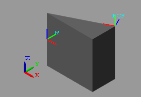
The figure shows a top view of the three-sided extrusion you model in this tutorial. You align the primary axis (z) with the surface normal vector nz and the secondary axis (x) with the line vector nx. Because nx is not normal to the primary axis, the secondary axis is the projection of nx onto the normal plane of the primary axis.

Try It: Create a Custom Solid Frame
Create a frame on a solid using the frame-creation interface. The solid shape is a general extrusion with three unequal sides. This shape helps to demonstrate the difference between the primary and secondary frame axes that you specify in the frame creation interface.
Specify the Solid Shape
From the Body Elements library, add one Extruded Solid block to a new model. The Extruded Solid block provides its own visualization utility. You do not need to update the block diagram to visualize the solid shape or its frames.
In the Extruded Solid block dialog box, specify these parameters.
Parameter Value Geometry > Cross-section [0,0;1,0;1,0.5]In the visualization toolstrip, select the Update Visualization button
 . The visualization pane updates with the three-sided extrusion that you specified.
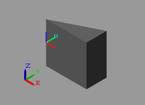
Select the Toggle visibility of frames button. The visualization pane shows all the frames in the solid. At this point, the solid has a single frame—its reference frame. The reference frame origin coincides with the [0,0] cross-section coordinate in the midplane of the extrusion.
Create the Frame
In the Frames expandable area of the Extruded Solid block dialog box, select the Create button ![]() . The Solid block opens the frame-creation interface.
. The Solid block opens the frame-creation interface.
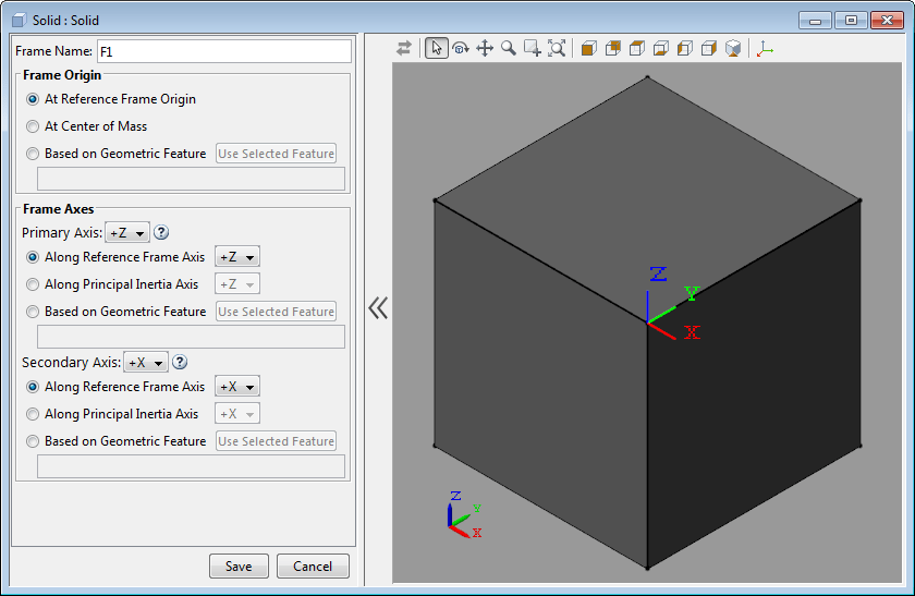
In the Frame Name parameter, enter ECF (short for Extrusion Corner Frame). The frame name identifies the new frame in the Solid block visualization pane. It also appears as the frame port label on the Solid block.
Specify the Frame Origin
Under Frame Origin, select At Center of Mass. The visualization pane updates with the new frame at the center of mass of the solid. This frame has the default frame orientation, that of the reference frame. The label ECF identifies the new frame.
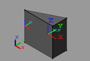
Experiment with other frame origin locations. Define the origin location using one of the extrusion vertices.
Under Frame Origin, select Based on Geometric Feature. This option enables you to select a point or the center of a plane or line as the frame origin.
In the visualization pane, select the vertex shown in the figure. The vertex is in the top plane of the extrusion. Ensure the view point is set to Isometric. In the Frame Origin area, ensure the vertex is named
Location of top point 3.Under Frame Origin, select the Use Selected Feature button. The visualization pane updates with the frame origin at the selected corner.
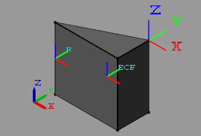
Specify the Primary Axis
The primary axis constrains the remaining two axes to lie on its normal plane. In this sense, the primary axis plays the dominant role in setting the orientation of the frame. Make the primary axis normal to the surface that contains the cross-section hypotenuse:
In the Frame Axes area under Primary Axis, select Based on Geometric Feature. The direction you specify in the next steps is that of the default primary axis,
+Z.In the visualization pane, rotate the solid and select the surface shown. The visualization pane highlights the surface and shows its normal vector. In the Frame Axes area under Primary Axis, ensure the surface is named
Surface normal of side surface 3.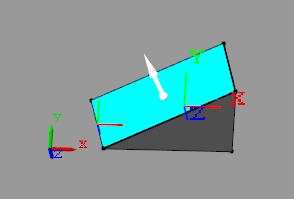
In the Frame Axes area under Primary Axis, select the Use Selected Feature button. The visualization pane updates with the z axis of the ECF frame, shown in dark blue, parallel to the normal vector of the selected surface.
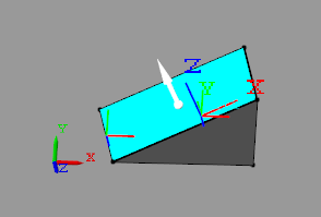
Specify the Secondary Axis
The secondary axis completes the definition of the new frame. In conjunction with the primary axis, the secondary axis fully constrains the direction of the third axis. The secondary axis is itself constrained to lie on the normal plane of the primary axis. To see the effects of this constraint, define the secondary axis based on a line not normal to the primary axis:
In the Frame Axes area, set the Secondary Axis parameter to
-X. The direction you specify in the following steps is that of the-Xaxis.In the Frame Axes area, under Secondary Axis, select Based on Geometric Feature.
In the visualization pane, rotate the solid and select the line shown. In the Frame Axes area, under Secondary Axis, ensure this line is named
Curve direction of top curve 1.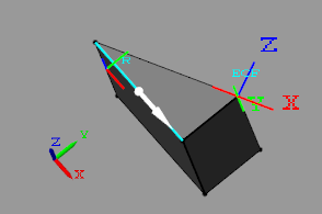
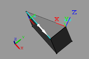
Select the Use Selected Feature button. The visualization pane updates wit the x axis of the frame, shown in red, partially aligned with the selected line.
The two are not completely aligned as the selected line does not lie on the normal plane of the primary axis. The secondary axis is therefore the projection of the selected line onto the normal plane of the primary axis.
Save the New Frame
To save the frame you defined and commit it to the model:
Select the Save button. The visualization pane shows the solid with the final version of the frame you defined.
In the main interface of the Solid block dialog box, select OK or Apply. The Solid block commits the new frame to the model and exposes a new frame port labeled with the frame name you specified.
