Working with Frames
Frames are axis triads that encode position and orientation data in a 3-D multibody model. Each triad consists of three perpendicular axes that intersect at an origin. The origin determines the frame position and the axes determine the frame orientation. The axes are color-coded, with the x-axis in red, the y-axis in green, and the z-axis in blue.

Role of Frames
Every solid component has one or more local frames to which it is rigidly attached. By positioning and orienting the component frames, you position and orient the components themselves. This is the role of frames in a model—to enable you to specify the spatial relationships between components.

Working with Frames
A frame port identifies a local frame on a component. For example, the R frame port of a solid block identifies the local reference frame of a solid. Every block has one or more frame ports that you connect in order to locate the associated components in space. The figure shows the reference frame ports on several of the Body Elements blocks.

The connections between frame ports determine the spatial relationships between their frames. A direct frame connection line makes the connected frames coincident in space. A Rigid Transform block sets the rotational and translational offsets between the frames. The figure shows examples of coincident and offset frame connections.
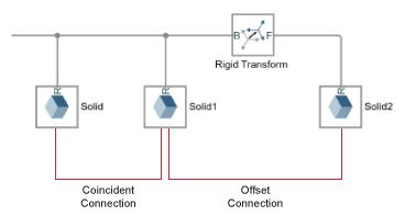
A coincident relationship between solid frames does not, by itself, constitute a coincident relationship between solid geometries. The spatial arrangement of two solid geometries depends not only on the spatial arrangement of the respective reference frames, but also on how the geometries are defined relative to those frames.
If two geometries differ from each other, or if their positions and orientations relative to their reference frames differ from each other, then making the reference frames coincident will cause the solid geometries to be offset. In the figure, connecting the frame of Solid A to the left frame of Solid B joins the solids such that their geometries are offset from each other.

Custom Solid Frames
The Solid block provides a frame creation interface that you can use to create new, custom, frames. You can position and orient a custom frame using geometry features such as vertices, edges, and faces. More conveniently from an inertia standpoint, you can do the same using the center of mass and three principal axes of the solid.
Try It: Create a Custom Solid Frame
Create a custom frame using the frame creation interface of the File Solid block. Then, place the frame origin at the center of mass and align the frame axes with the principal axes of inertia. The result is a frame that coincides with the principal reference frame—one in which the inertia matrix is diagonal and the products of inertia are zero.
At the MATLAB® command prompt, enter
openExample("sm/DocLBeamInertiaExample"). A model opens with a solid possessing the shape of an L-beam.In the File Solid block dialog box, click the Create Frame button. The File Solid block dialog box switches to a frame creation view.
Change the Frame Name parameter to
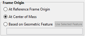
P(for “Principal Frame”). The visualization pane and the frame port use this label to identify your new frame.Under Frame Origin, select the radio button labeled At Center of Mass.
Under Frame Axes > Primary Axis and Frame Axes > Secondary Axis, select the radio button labeled Along Principal Inertia Axis. Accept the default axis options (
+Zand+X, respectively) and click Save. The block dialog box switches back to the main (parameters) view.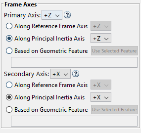
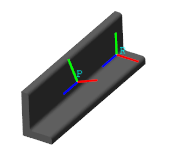
In the visualization toolstrip, click the Toggle visibility of frames button. The visualization pane shows the frames of the solid, including your new custom frame, P.
Frame Transforms
The rotational and translational offsets between frames are called transforms. If the transforms are constant through time, they are called rigid. Rigid transforms enable you to fix the relative positions and orientations of components in space.

Working with Frame Transforms
You use the Rigid Transform block to specify a rotational, translational, or mixed rigid transform between frames. The transforms are directional. They set the rotation and translation of a frame known as follower relative to a frame known as base.
The frame port labels on the Rigid Transform block identify the base and follower frames. The frame connected to port B serves as base. The frame connected to port F serves as follower. Reversing the port connections reverses the direction in which the frame transform is applied.

You can specify a transform using different methods. For rotational transforms, these include axis-angle pairs, rotation matrices, and rotation sequences. For translational transforms, they include translational offset vectors defined in Cartesian or cylindrical coordinate systems.
If the rotational and translational transforms are both zero, the connected frames are coincident in space. This relationship is known as identity and it is equivalent to a direct frame connection line between frame ports.
Visualizing Frame Transforms
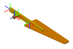
You can visualize frames and examine the transforms between frames using the Solid block visualization pane or Multibody Explorer. Use the Solid block visualization pane to examine the frames of a single solid element. Click the Toggle visibility of frames button in the visualization toolstrip to show all the solid frames.
A Frame on a Solid

Use Multibody Explorer to visualize the frames of more than a single solid element—e.g., in compound bodies, multibody subsystems, or complete multibody models. Select View > Show Frames in the Multibody Explorer menu to show all frames. Select a node from the tree view pane to show only those frames belonging to the selected component.
Frames on a Body
Specify a Frame Transform
This example shows how to offset two solids relative to each other by specifying a frame transform between the solid reference frames. It shows three types of transformations: translation, rotation, and combined transformation.
Create a Model with Two Solids
At the MATLAB command line, enter
smnew. A Simscape™ Multibody™ model template with commonly used blocks opens.Delete the Simulink-PS Converter, PS-Simulink Converter, and Scope blocks because they are not used in this example.
Show the names of the Rigid Transform and Brick Solid blocks. Right-click the blocks and select Format > Show Block Name > On.
Make a copy of the Brick Solid block and rename the Brick Solid blocks to Base and Follower.
Connect the remaining blocks like the following figure.

Run the model. Multibody Explorer opens with a model visualization. In the Multibody Explorer, click the Isometric view button.
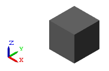
In the tree view pane, click the Base and Follower nodes. The visualization pane shows the reference frames of the two Brick Solid blocks, which shows they are coincident in space.
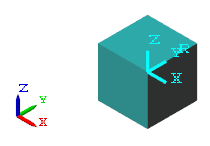
Apply a Translation
This section shows how to apply a translation to a follower frame by using the Rigid Transform block.
Connect the Rigid Transform block between the two Brick Solid blocks.

Double-click the Rigid Transform block. In its dialog box, set:
Translation > Method to
Cartesian.Translation > Offset to
[1 1 0]m. The array elements are the translation offsets along the base frame x, y, and z-axes.
Click OK to save the settings and close the Rigid Transform dialog box.
Click Update diagram button in the Multibody Explorer to update the model.
In the tree view pane, click the Rigid Transform node to show the Base and Follower frames.

Apply a Rotation
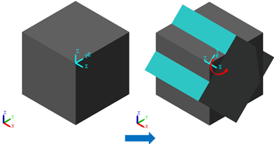
This section shows how to apply a rotation about the x-axis to the follower frame by using the Rigid Transform block.
In the Rigid Transform block dialog box, set:
Translation > Method to
None. No translation is specified here.Rotation > Method to
Standard Axis.Rotation > Axis to
+X. x-axis is the axis of rotation.Rotation > Angle to
45deg.
Click OK and update the block diagram.
In the tree view pane, click the Rigid Transform node. The following figure shows the process and the final result of the rotation. In the final result, the Follower brick solid is highlighted.
Apply a Combined Transformation
This section shows how to apply a combined transformation, which includes a translation and a rotation to a follower frame by using the Rigid Transform block.
In the Rigid Transform block dialog box, set:
Translation > Method to
Cartesian.Translation > Offset to
[1 1 0].Rotation > Method to
Standard Axis.Rotation > Axis to
+X. x-axis is the axis of rotation.Rotation > Angle to
45deg.
Click OK and update the block diagram.
In the tree view pane, click the Rigid Transform node. The following figure shows the process and the final result of the combined transformation.

When both rotational and translational transformations are specified in a Rigid Transform block, the block always applies the translation to the follower frame first. The translations describe how the follower frame is moved relative to its base frame. Any rotations about the base frame axes are always in respect to the axes of the translated base frame.