Visualize a Model and Its Components
Visualize a Complete Multibody Model
Model visualizations open in Multibody Explorer—the Simscape™ Multibody™ visualization utility. By default, Multibody Explorer starts automatically when you first update a model (in the Modeling tab, click Update Model) or simulate a model. To change this setting, see Enable Multibody Explorer.
The visualizations consist of the multibody subassemblies, compound bodies, and simple bodies present in your models. Multibody Explorer displays model entities such as solid geometries, spline curves, inertia icons, and frames. You can selectively show and hide individual entities using the context-sensitive menu of the Multibody Explorer tree view pane. See Selective Model Visualization.
A visualization is static when you update a model and dynamic when you simulate a model. The
static visualization in this case shows the model in its initial configuration,
with the joints in their initial states. The dynamic visualization shows a 3-D
animation that you can record—using either Video Creator or the
smwritevideo function—see Create a Model Animation Video.
You can manipulate the viewpoint using the tool strip located above the visualization pane. The tool strip enables you to rotate, roll, pan, and zoom the model view. A Camera Manager enables you to create dynamic cameras that move with the model to keep it in view during simulation—see Visualization Cameras.
Visualize a Multibody Model
At the MATLAB® command prompt, enter
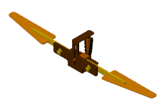
openExample('sm/PointOnCurveExample'). The model shown in the flapping-wing featured example opens.In the Modeling tab, click Update Model. Multibody Explorer opens with a view of the model in its initial state.

Click Run. Multibody Explorer plays an interactive 3-D animation based on the simulation results.

A Note About Inertia Ellipsoids
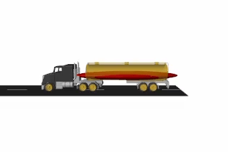
Equivalent inertia ellipsoids provide an intuitive means to visualize variable inertias (modeled using the General Variable Mass block). These ellipsoids are rendered dynamically, with their dimensions and poses obtained at each time step from the specified instantaneous inertial properties. Ellipsoid visualization is not available on model update. Variable inertial properties are specified through physical signals whose values are inaccessible to the blocks until the simulation begins.
Inertia Ellipsoid in a Tank Truck Model

Visualize an Individual Solid Geometry
Blocks such as Brick Solid and Spline provide visualization panes that show the geometries specified in the block Parameters sections. Use the block visualizations to catch geometry errors as they occur—for example, incorrect dimensions, colors, and, in solid blocks, frame placements.
The block visualizations are similar to those provided in Multibody Explorer. You
can rotate, roll, pan, and zoom the view using a tool strip located above the
visualization pane. The tool strip includes buttons for standard views such as
Front, Top, and
Isometric. You can show or hide the frames of the
block.
You can refresh block visualizations without updating or simulating a model. The visualizations refresh the moment you click the Update Visualization button in the visualization tool strip. Using MATLAB variables in block parameters does not affect your ability to refresh a visualization.
Visualize a Solid
At the MATLAB command prompt, enter
smnewto open the Simscape Multibody model template. The template contains commonly used blocks, including the Brick Solid block.Open the Brick Solid block dialog box. The visualization pane is by default expanded to show an isometric view of the default solid—a gray brick.

Set the Graphic > Color parameter to
[0.5 0 0]—an RGB vector corresponding to a dark red color.Click the Update Visualization button, located above the solid visualization pane. The visualization updates to show what is now a red brick.

A Note on Imported Geometries
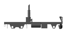
You can import solid geometries from STEP or STL files. Corrupt or invalid geometry files cause visualization and simulation issues. Geometries associated with such files are not shown during model visualization. The corresponding solid inertias cannot be automatically computed from the solid geometries and the simulation fails if the Inertia > Type parameter is set to Calculate from Geometry.
An Imported Solid Geometry
