User-Added Coordinate Systems
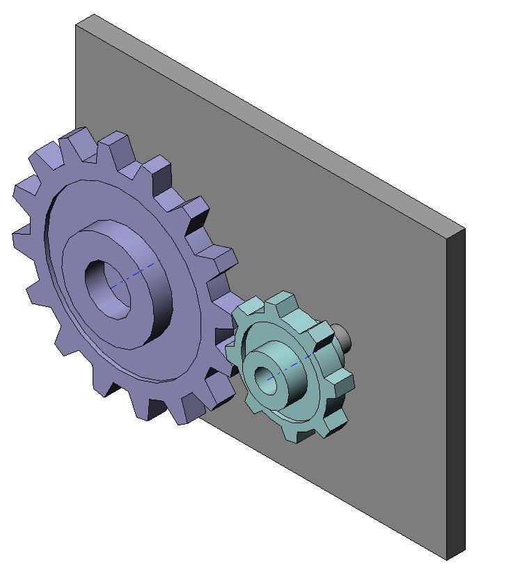
This example shows how to define the coordinate system to recreate a constraint in the generated Simscape™ Multibody™ model. In this assembly, two gear parts mesh with a gear ratio of 2:1. The two gear parts are constrained by a Gear mate in the SolidWorks® assembly. Because the Simscape™ Multibody™ Link exporter does not support this constraint, exporting this assembly results in an XML file in which the gear constraint is replaced by a rigid connection between the two parts. You can define your own coordinate systems in order to easily recreate this constraint when you generate the Simscape Multibody model.
To do this, each of the two gear parts has a user-defined coordinate system that will be exported to the XML file. Both these coordinate systems should have the same prefix (here, SMLINK_). In the Simscape Multibody Link Settings menu in SolidWorks®, set the "Export Coordinate Systems" radio-button to "Export only CSs with this prefix" and enter "SMLINK_" in the edit field below the button. This ensures that both the coordinate systems labelled as SMLINK_CS1 and SMLINK_CS2 are exported to the XML file.
After export, open the XML file to see the two exported coordinate systems. When you generate a Simscape Multibody model from this XML file, the user-defined coordinate systems will appear as unconnected ports on the blocks representing the gear parts. A rigid connection is automatically inserted between the two blocks for the unsupported Gear constraint.
CAD Software Requirements
This CAD assembly can be opened in SolidWorks® 2007 and higher.
Assembly
To see the assembly, in the CoordinateSystemsSWSupport/Geometries folder, open the GearAssembly.SLDASM.
