Export Custom Reference Design
This example shows how to export a custom reference design from an SoC model by using the Soc Blockset™ socExportReferenceDesign function. After creating the custom reference design, use the HDL Workflow Advisor tool from HDL Coder™ to integrate an IP core into the reference design.
Design Task
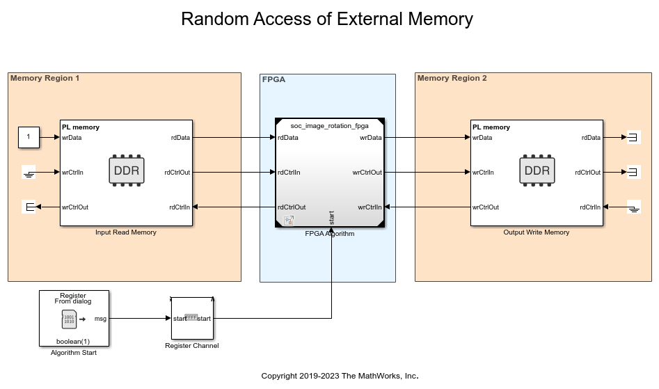
This example uses the model soc_image_rotation to generate a custom reference design. The model has an external memory and an FPGA DUT. The DUT contains an AXI4 master read interface and an AXI4 master write interface to perform read and write operations to memory. For a full description of the model, see Random Access of External Memory. The model also uses an socAXIManager to read and write the external memory from the host computer.
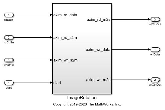
When exporting a custom reference design from this model, the DUT is not included in the reference design, and the interface to the DUT is exposed. After generating the reference design you can integrate your custom IP by using the HDL Workflow Advisor tool. Your custom IP must have the same interface as the FPGA Algorithm block.
Open the model to view the structure of the top model and the interface to the FPGA Algorithm block.
open_system('soc_image_rotation');

Prepare SoC Model for Custom Reference Design Export
In Simulink®, open the Configuration Parameters dialog box by clicking Model Settings on the Modeling tab. Then, follow these steps to prepare the SoC model for custom reference design export.
On the left pane, select Hardware Implementation.
Set Hardware board to match your board (if you are not using
Xilinx Zynq ZC706 evaluation kit).Under Feature set for selected hardware board, select SoC Blockset. If this parameter is not visible for your board, skip this step.
Expand Target hardware resources, select FPGA design (top-level), and then select Include AXI Manager IP for host-based interaction.
Because this SoC model does not include a processor, clear Include processing system. If your SoC model includes a processor subsystem, then select this option.
In the IP core clock frequency (MHz) box, specify the IP core clock frequency in MHz.
Export Custom Reference Design
Export the custom reference design for model soc_image_rotation by using the socExportReferenceDesign function. Enter this code at the MATLAB command prompt:
socExportReferenceDesign('soc_image_rotation')
The function generates these artifacts in the current folder.
Board registration files
Reference design registration file
IP repository
Design files
Constraint files

Add Generated Design Folder to Path
To add the generated design folder to the MATLAB path, right click on the folder named top-model-refdesign, where top-model is the name of the top SoC model. Then select Add to Path>Selected Folders and Subfolders.
Integrate IP Core into Custom Reference Design
After generating a reference design, you can save it or pass it to the IP developer for integration and deployment of their IP on a board.
This example uses the image rotation DUT as the IP. This reference design is suitable for any IP that has the same interface.
open_system('soc_image_rotation_fpga');

In Simulink, right-click the ImageRotation block and select HDL Code>HDL Workflow Advisor to open the HDL Workflow Advisor tool.
In step 1.1, set Target workflow to
IP Core Generationand Target platform to the platform generated by thesocExportReferenceDesignfunction. For this example, selectXilinx Zynq ZC706 evaluation kit (generated by SoC Blockset).Click Run This Task.
Select step 1.2. Note that Reference design is set to
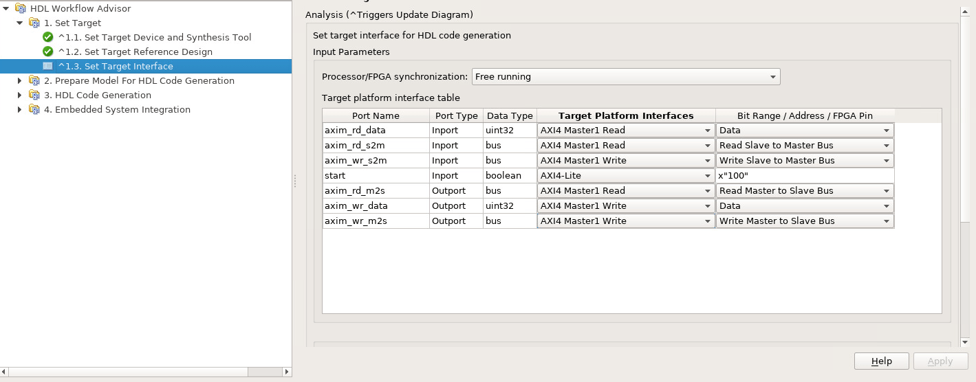
Design exported from 'soc_image_rotation' model.In step 1.3, set the target interface by connecting each port in your IP to the corresponding port in the reference design.

5. Continue with the remaining steps of the HDL Workflow Advisor tool.
6. In step 4.2, under Generate a software interface model with IP core driver blocks for C code generation, select Skip this task. For this example, select this value because the generated reference design includes only FPGA and memory components. If the reference design also includes a processing system, clear this option.
7. In step 4.4, set Programming method to JTAG.
8. Connect the host machine to a ZC706 board, and follow the workflow to load your full design (IP and custom reference design) to the FPGA.
9. Use AXI Manager to interact with the FPGA from the host machine.
Conclusion
This example covered these workflows.
Generating a reference design from an SoC model
Integrating an IP core into the generated reference design using the HDL Workflow Advisor tool
See Also
socExportReferenceDesign | SoC Builder