Getting Started with SoC Blockset Support Package for Infineon AURIX Microcontrollers
This example shows how to use SoC Blockset™ Support Package for Infineon® AURIX™ Microcontrollers to configure a simple Simulink model to generate code for Infineon® AURIX™ TC4x and to run the generated code on the board to periodically turn an LED on and off in different patterns based on pressing a user button (black button).
Introduction
SoC Blockset™ Support Package for Infineon® AURIX™ Microcontrollers includes a library of Simulink blocks that you can use to configure and access Infineon AURIX TC4x Microcontrollers peripherals and communication interfaces.
Supported Hardware
Infineon AURIX TC4x - TriBoards
Required Software
Launch hardware setup and install the following third-party tools. For more information, see Supported Hardware and Required Software.
iLLD for TC4x family
TASKING SmartCode for TriCore
Infineon MemTool
Synopsys® MetaWare for Infineon AURIX TC4x
Required Hardware
To run this example, you will need the following hardware:
Supported Infineon AURIX TC4x board (STD or COM)
USB cable
Simulink Model
Open the tc4x_8ledsBlinky.slx model.
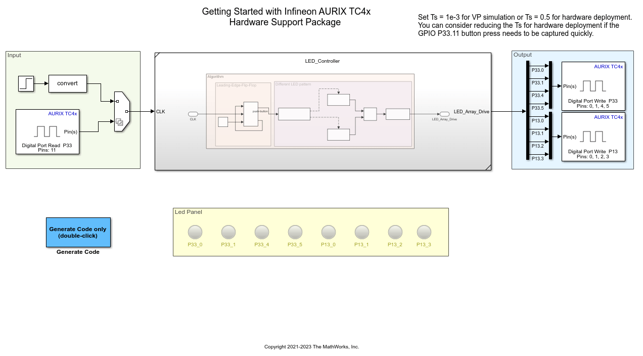
This example demonstrates how to make an LED light blink in two patterns. The two patterns are controlled by an input switch, switch P33.11 connected to the board.
The different patterns can be observed on the eight LEDs connected to the onboard (P33.0, P33.1, P33.4, P33.5, P13.0, P13.1, P13.2, P13.3). When the switch detects a leading edge, the output of the D Flip-Flop block toggles between 0 and 1.
The model generates Pattern 1, when the D flip-flop outputs 0 and Pattern 2 when it outputs 1.
Pattern 1: LEDs blink from right to left and vice versa.
Pattern 2: LEDs on the alternate pins blink.
Review Infineon Block Library
SoC Blockset™ Support Package for Infineon® AURIX™ Microcontrollers enables you to create algorithms by using the blocks that you can add to your Simulink® model. The blocks are used to configure the associated sensors and actuators, as well as to read and write data to sensors and actuators.
1. Enter slLibraryBrowser at the MATLAB® prompt. This opens the Simulink Library Browser.
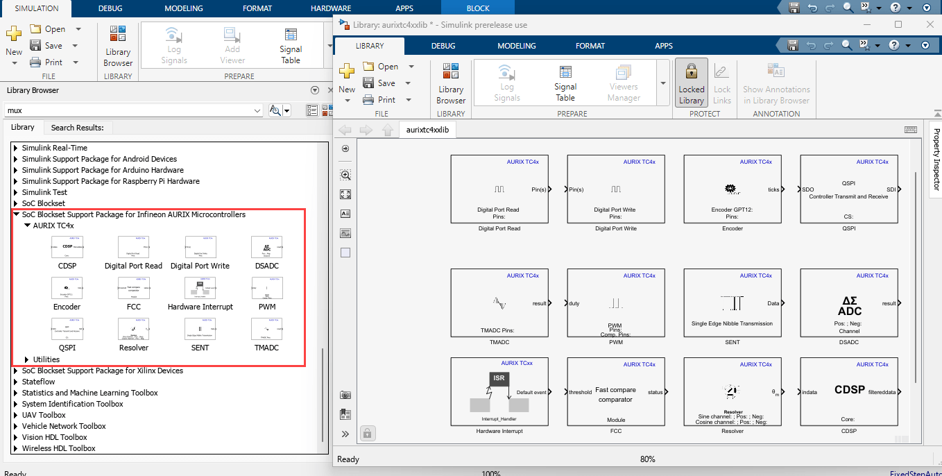
2. In the Simulink Library Browser, navigate to SoC Blockset Support Package for Infineon AURIX Microcontrollers > AURIX TC4x.
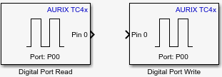
3. Double-click the Digital Port Read and Digital Port Write blocks. Review the block mask, which contains a description of the block and parameters for configuring the associated Infineon digital output pin.
Configure and Run the Model on Supported Infineon Hardware
In this task, you will configure and run your model on the supported Infineon AURIX™ board.
1. Connect the Infineon board to your computer with a USB cable.
2. In your Simulink model, press Ctrl+E or click Modeling > Model Settings to open Configuration Parameters dialog box.
3. Select the Hardware Implementation pane and select your required Infineon hardware from the Hardware board parameter list. Do not change any other settings.
4. Enter the following command in the MATLAB® prompt:
For Virtual Prototyping(VP) simulation:
Ts = 1e-3
For hardware deployment:
Ts = 1
5. Click OK.
Generate Code for Microcontroller
1. To generate the code for the tc4x_8ledsBlinky.slx model, press Ctrl+B or click Build.
2. Follow the build process by opening the diagnostic viewer using the link provided at the bottom of the model canvas.
3. Click Configure, Build, Deploy & Start on the Hardware tab of the top model to launch the SoC Builder tool. Complete the steps as mentioned in the tool.
Other Things to Try
Run the example on different Infineon AURIX TC4x Microcontrollers by changing the package class and pinout options and analyze the results.
More About
You can also select a web site from the following list:
Americas
- América Latina (Español)
- Canada (English)
- United States (English)
Europe
- Belgium (English)
- Denmark (English)
- Deutschland (Deutsch)
- España (Español)
- Finland (English)
- France (Français)
- Ireland (English)
- Italia (Italiano)
- Luxembourg (English)
- Netherlands (English)
- Norway (English)
- Österreich (Deutsch)
- Portugal (English)
- Sweden (English)
- Switzerland
- United Kingdom (English)