Integrate MCU Scheduling and Peripherals in Motor Control Application
This example shows how to identify and resolve issues with respect to peripheral settings and task scheduling early during development.
The following are typical challenges associated with MCU peripherals and scheduling:
ADC-PWM synchronization to achieve current sensing at mid point of PWM period
Incorporate sensor delays to achieve the desired controller response for the closed loop system
Studying different PWM settings while designing special algorithms
This example shows how to use C2000 Microcontroller Blockset to address these challenges for a motor control closed-loop application in simulation and verify on hardware by deploying on to the TI Delfino F28379D LaunchPad.
Required hardware:
TI Delfino F28379D LaunchPad or TI Delfino F2837xD based board
BOOSTXL-DRV8305EVM motor driver board
Teknic M-2310P-LN-04K PMSM motor
Model Structure
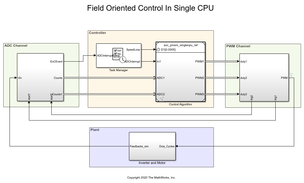
Open the soc_pmsm_singlecpu_foc.slx. This model simulates single CPU motor controller, contained in soc_pmsm_singlecpu_ref.slx, for a Permanent magnet synchronous motor inverter system. Controller senses the outputs from the plant using ADC Interface (C2000 Microcontroller Blockset) and actuates using PWM Interface (C2000 Microcontroller Blockset) that drives the inverter. Algorithm blocks from Motor Control Blockset™ is used in this example.
ADC Acquisition Time
ADC hardware contains a sample and hold circuit to sense the analog inputs. To ensure complete ADC measurement, the minimum acquisition time must be selected to account for the combined effects of input circuit and the capacitor in the sample and hold circuit.
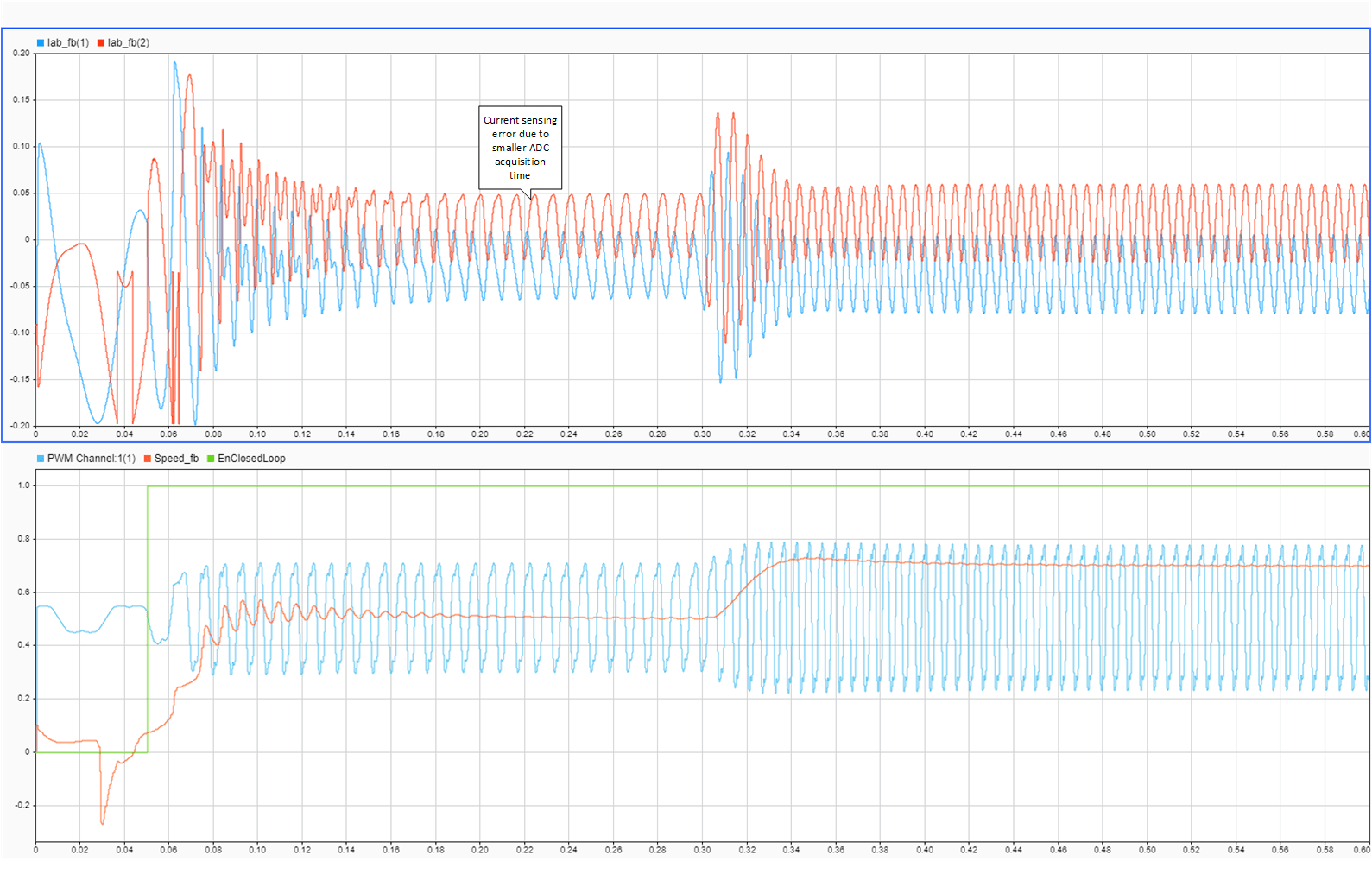
Open ADC Interface block and change the default acquisition time to 100ns. Run the simulation and view the results in Simulation Data Inspector and observe there is a distortion in current waveforms. The low acquisition time resulted in ADC measurements not reaching their true value. As a result, the controller reacts by generating a relative duty cycle causing variations in current drawn by the motor. These figures show the reaction to the incorrect ADC measurement and overdraw in the phase A current channel, with phase A current in blue and phase B current in orange. The simulated speed feedback shows significant oscillations during open loop to closed loop transition, which in real world will halt the motor.
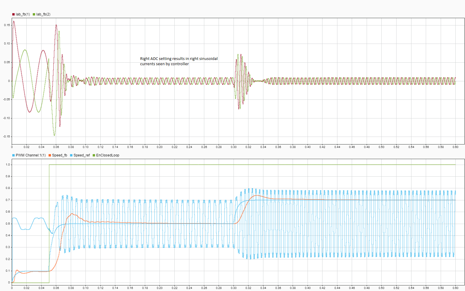
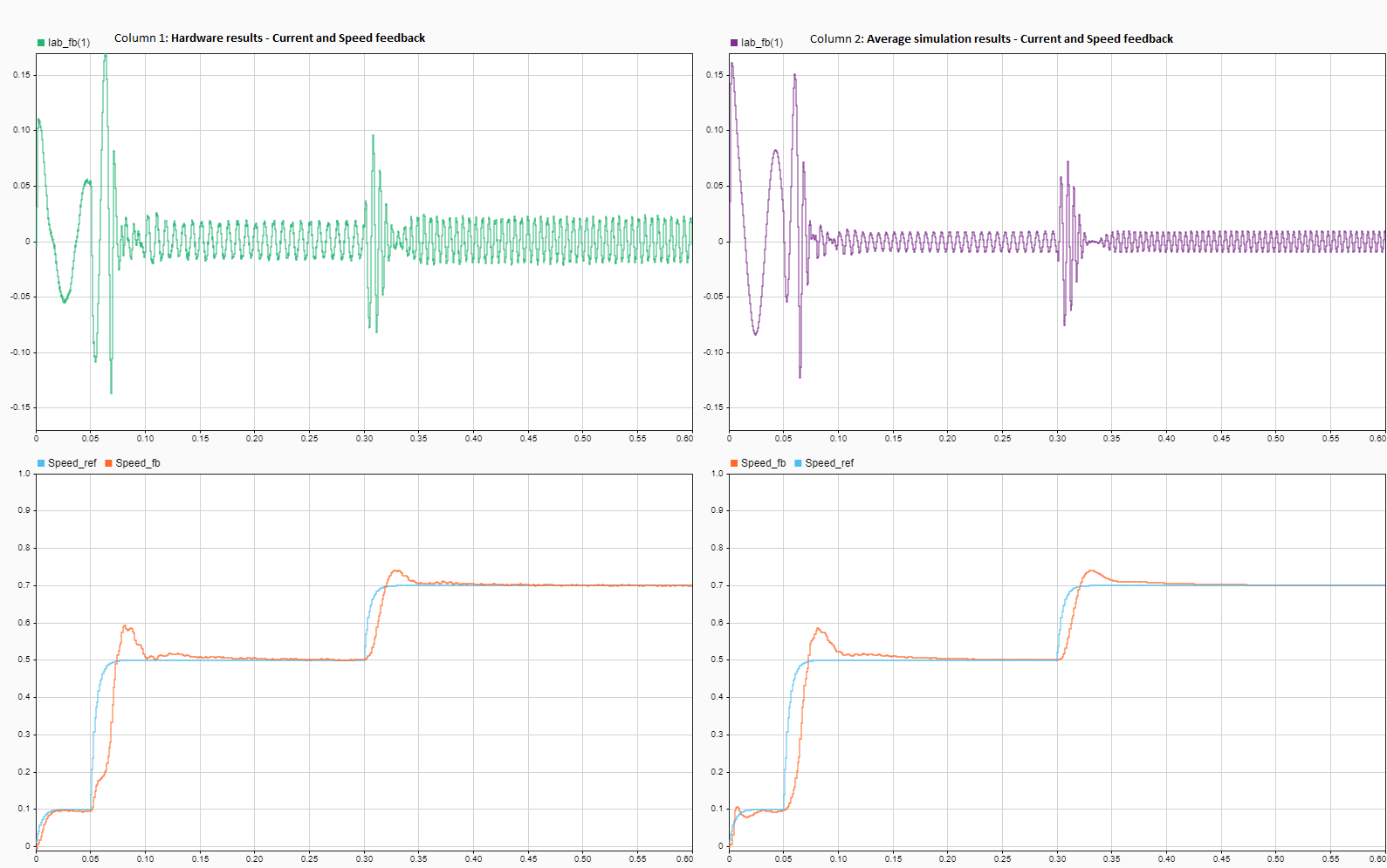
To fix this issue, open ADC Interface blocks change and change acquisition time to a larger value, 320ns. This value is above the minimum ADC acquisition time recommended in section ADC Operating Conditions (12-Bit Single-Ended Mode) of the TI Delfino F28379D LaunchPad data sheet. Run the simulation and view the results in Simulation Data Inspector. This figure shows the accurately sampled ADC values and the controller tracking the reference value as expected.
Verify the simulation results against hardware by deploying the model to the TI Delfino F28379D LaunchPad. On the System on Chip tab, click Configure, Build, & Deploy to open the SoC Builder tool.
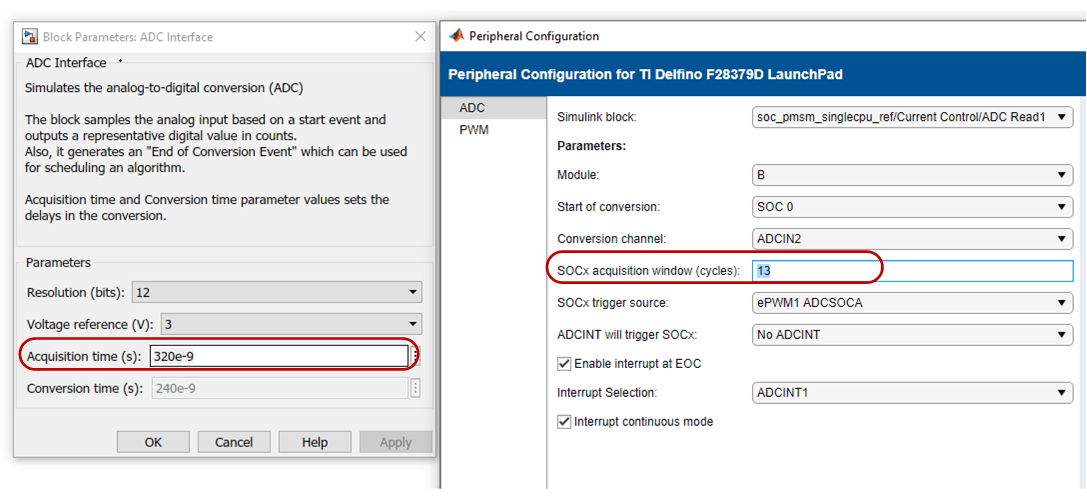
In the SoC Builder tool, on Peripheral Configuration tool, set ADC > SOCx acquisition window cycles parameter to 13 ADC clock ticks for the ADC B and C modules. The ADC acquisition clock ticks parameter must be set to the simulation time value, set in the ADC Interface block, multiplied by the ADC clock frequency. You can get the ADC clock frequency from the model hardware settings. Open the soc_pmsm_singlecpu_ref model. On the System on Chip tab, click Hardware Settings to open the Configuration Parameters window. In the Hardware Implementation > Target hardware resources > ADC_x section, you can see the ADC clock frequency in MHz parameter value. This figure shows the ADC Interface block setting for simulation and peripheral app setting for deployment. Use same setting in simulation and code generation to ensure expected behavior.
On Select Build Action page, to monitor data from hardware select Build and load for External mode. This figure shows the data from hardware with accurately sampled ADC values and the controller tracking the reference value as expected.
ADC-PWM Synchronization
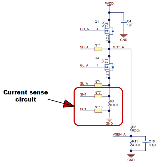
The BOOSTXL-DRV8305EVM motor driver has a 3-phase inverter built using 6 power MOSFETS. This motor driver board uses a low-side shunt resistor to sense motor currents. The Current sense circuit amplifies the voltage drop across the shunt. This setup ensures low power dissipation, since the current only flows through the shunt when the bottom switches are on and away from PWM commutation noise. This figure shows the low-side shunt resistor circuit in BOOSTXL-DRV8305EVM motor drive.
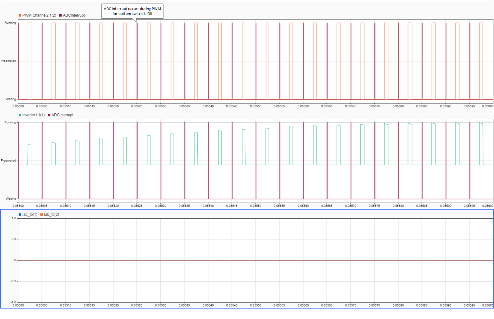
For correct operation, current sensing must occur during the mid point of the PWM period when ADCs trigger. Specifically, the PWM counter must be at the maximum value when the bottom switches are active in the Up-Down counter mode. Current sampling at a different instance results in a measured currents of zero.
To analyze this case, switch the model to high fidelity inverter simulation mode. Change the plant variant to use detailed MOSFET based 3-phase inverter to replicate BOOSTXL-DRV8305EVM.
set_param('soc_pmsm_singlecpu_foc/Inverter and Motor/Average or Switching',...
'LabelModeActivechoice','SwitchingInverter');
Change the Output mode parameter of PWM Interface (C2000 Microcontroller Blockset) to Switching and connect 6 PWMs to the Mux block.
set_param('soc_pmsm_singlecpu_foc/PWM Channel/PWM Interface', 'OutSigMode', 'Switching');
set_param('soc_pmsm_singlecpu_foc/PWM Channel/PWM Interface1', 'OutSigMode','Switching');
set_param('soc_pmsm_singlecpu_foc/PWM Channel/PWM Interface2', 'OutSigMode', 'Switching');
Delete existing connection between PWM Interface block and Mux.
h = get_param('soc_pmsm_singlecpu_foc/PWM Channel/Mux','LineHandles');
delete_line(h.Inport);
As a last step, connect 6 PWM outputs to Mux.
set_param('soc_pmsm_singlecpu_foc/PWM Channel/Mux','Inputs','6');
add_line('soc_pmsm_singlecpu_foc/PWM Channel', ...
{'PWM Interface/1', 'PWM Interface/2', 'PWM Interface1/1',...
'PWM Interface1/2', 'PWM Interface2/1', 'PWM Interface2/2'}, ...
{'Mux/1','Mux/2','Mux/3','Mux/4','Mux/5','Mux/6'}, 'autorouting', 'smart');
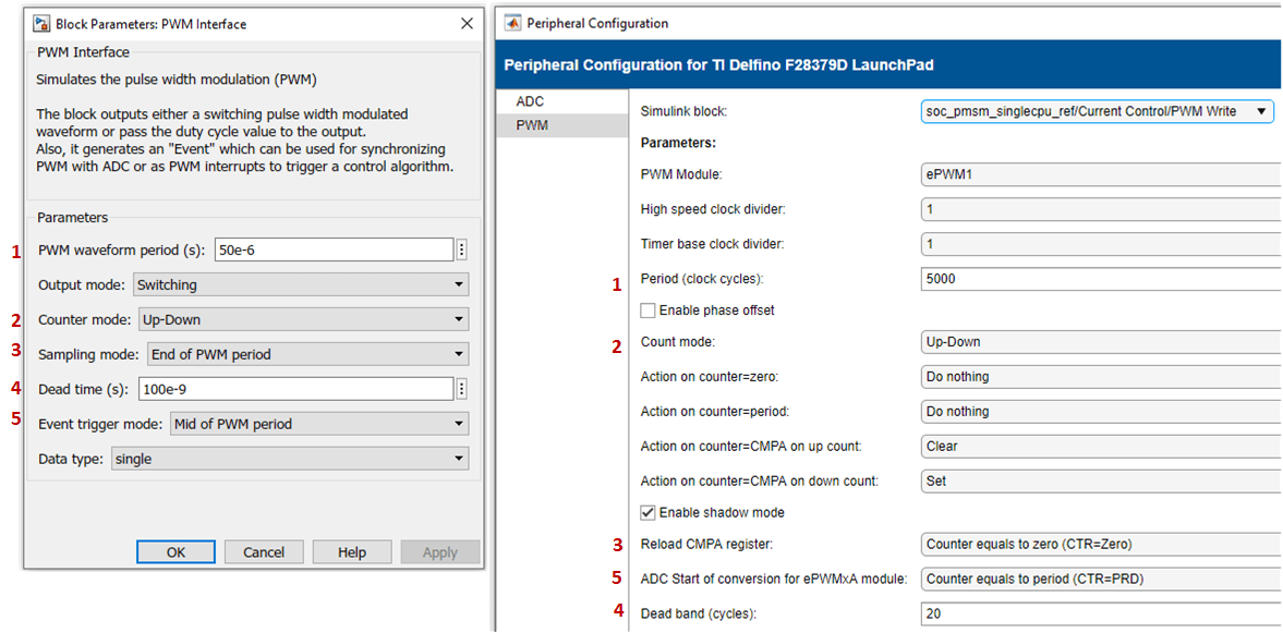
Open the PWM Interface blocks and set Event trigger mode to End of PWM period. Run the simulation and view the results in Simulation Data Inspector. In the figure, phase A and phase B currents are approximately zero current. This results in a loss of feedback and no actuation in the control loop. Select Enable task simulation in Task Manager block to simulate and visualize tasks in Simulation Data Inspector.
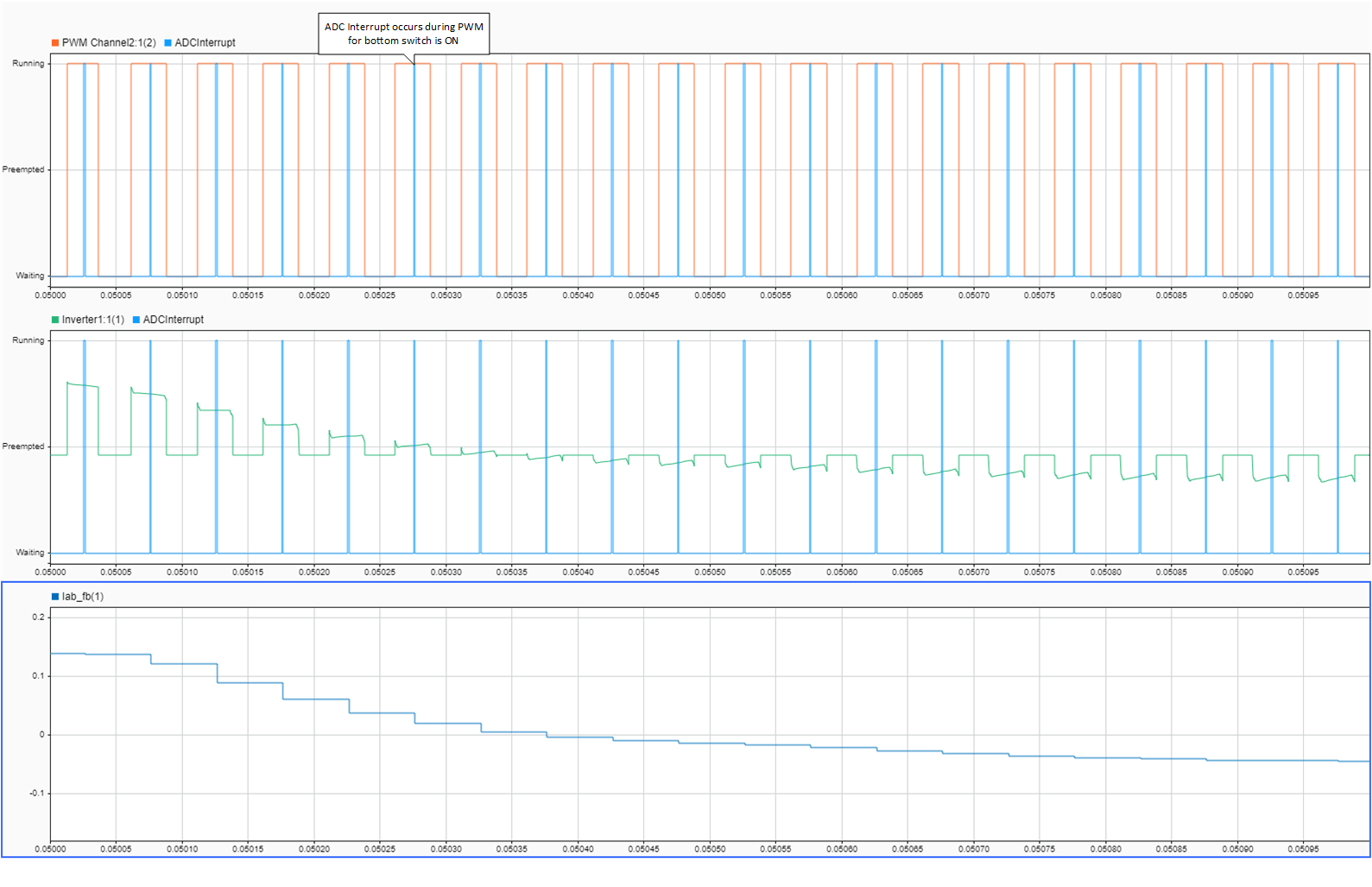
To fix this issue, change the Event trigger mode to Mid point of PWM period, equivalent to the PWM internal counter being at a maximum. Run the simulation and view the results in Simulation Data Inspector.
Deploy the model on to the TI Delfino F28379D LaunchPad using the SoC Builder tool. In the SoC Builder tool, on Peripheral configuration tool, set PWM event condition to Counter equals to period. Use same setting in simulation and code generation to ensure expected behavior. This figure shows the PWM Interface block setting for simulation and the Peripheral Configuration tool setting for deployment.
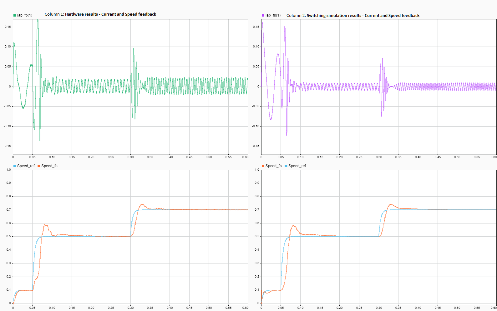
This figure shows the data from simulation and hardware with correct ADC-PWM synchronization and the controller tracking the reference value as expected.
Copyright 2020-2023 The MathWorks, Inc.