Multicore Implementation of Pulse-Doppler Radar
This example shows how to implement a pulse-Doppler radar system using multiple processor cores on the Xilinx® Zynq® UltraScale+™ RFSoC evaluation kit. The example builds upon Pulse-Doppler Radar Using AMD RFSoC Device that uses a single processor core.
Supported Hardware Platforms
Xilinx Zynq UltraScale+ RFSoC ZCU111 evaluation kit + XM500 balun card
Application Structure
This example models a complete range-Doppler processing system that includes a transmitter, a receiver, and a radar target emulator.
This application implements the transmitter and the target emulator on the FPGA core. The receiver applies the range and Doppler processing to the emulated signals and estimates the range and velocity. The FPGA core calculates the range, while the processor core estimates the velocity.
The SoC model soc_range_doppler_mc_top includes the model references to the FPGA model soc_range_doppler_fpga and the processor model soc_range_doppler_mc_proc. The top model and the FPGA model are the same as in Pulse-Doppler Radar Using AMD RFSoC Device, while the processor model implements the velocity estimation using multiple processor cores.
open_system('soc_range_doppler_mc_top')

close_system('soc_range_doppler_mc_top')
Processor Model
The processor model in Pulse-Doppler Radar Using AMD RFSoC Device has four tasks:
baseRateTaskcontrols the timing execution of the processor software.radarTargetUpdateTaskconfigures and updates the radar target emulator.udpRxTaskreceives the configuration information from the host.dataReadTaskperforms the Doppler processing on the range data.
The first three tasks perform service functions, while the dataReadTask performs the main application task.
dataReadTask has three stages:
Data receipt from the FPGA core.
Unpacking of the received data.
Doppler processing of the data.
Most of the computation occurs in the Doppler processing stage which performs an FFT algorithm on a two-dimensional (2-D) data array (64 by 1024). One way to achieve better efficiency is to implement Doppler processing on multiple cores.
Multicore Implementation
The Doppler processing stage has two tasks that can run on two different cores. Each of these tasks runs an FFT algorithm on a smaller 2-D matrix (64 by 512). These matrices represent different halves of the original 2-D matrix (64 by 1024). Since the input data must be split and the results of two processing tasks must be joined, the following tasks replace the original dataReadTask:
dataReadTaskreceives the FPGA data, unpack and split the matrix.dataProc1Taskperforms an FFT algorithm on the first half of the matrix.dataProc2Taskperforms an FFT algorithm on the second half of the matrix.dataJoinTaskjoins the results of two FFT algorithms.
The two processing tasks, dataProc1Task and dataProc2Task, run on two different cores. To get the correct overall results, the tasks must be synchronized with other tasks.
open_system('soc_range_doppler_mc_proc')

close_system('soc_range_doppler_mc_proc')
Data Read Task
dataReadTask waits until it receives an FPGA data frame, then unpacks and splits it. Then, it triggers dataProc1Task and dataProc2Task using two Task Trigger blocks.
load_system('soc_range_doppler_mc_proc')
open_system('soc_range_doppler_mc_proc/dataReadTaskFcn/Process CPI')

close_system('soc_range_doppler_mc_proc')
Data Processing Task
dataReadTask triggers dataProc1Task and dataProc2Task. Once triggered, each task performs an FFT algorithm and sends a trigger to dataJoinTask using a Task Trigger block.
load_system('soc_range_doppler_mc_proc')
open_system('soc_range_doppler_mc_proc/dataProc1TaskFcn')

close_system('soc_range_doppler_mc_proc')
Data Join Task
The dataJoinTask waits for triggers from both dataProc1Task and dataProc2Task. A Task Trigger Merge block merges two triggers into one.
load_system('soc_range_doppler_mc_top')
open_system('soc_range_doppler_mc_top/Processor')

close_system('soc_range_doppler_mc_top')
Simulation
To confirm the basic operation, run the model and observe the estimated range and velocity of the moving targets on the Range Doppler Response and Detection Map plot.
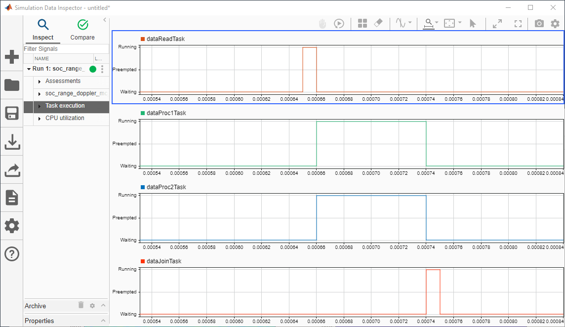
Open the Simulation Data Inspector and observe that two data processing tasks run in parallel on different cores and that they synchronize with dataReadTask and dataJoinTask.
Deployment
Set up the hardware and run the model on hardware as explained in Pulse-Doppler Radar Using AMD RFSoC Device.
The Range Doppler Response and Detection Map plot shows the estimated range and velocity of the moving targets.
Open the Simulation Data Inspector and the SoC Blockset Performance Report and observe that two data processing tasks run in parallel on different cores.
Use the Simulation Data Inspector cursors to measure the end-to-end processing time for a single data frame. Observe that the processing time of 37 ms represents a significant improvement over 54 ms processing time measured in the single-core implementation in Pulse-Doppler Radar Using AMD RFSoC Device.
Conclusion
This example shows how to implement a pulse-Doppler radar system using multiple processor cores on the Xilinx Zynq UltraScale+ RFSoC evaluation kit. The example demonstrates that the multicore implementation achieves better CPU utilization and allows for increasing the system requirements.