Multiband Power System Stabilizer
(To be removed) Implement multiband power system stabilizer
The Specialized Power Systems library will be removed in R2026a. Use the Simscape™ Electrical™ blocks and functions instead. For more information on updating your models, see Upgrade Specialized Power System Models to use Simscape Electrical Blocks.
Libraries:
Simscape /
Electrical /
Specialized Power Systems /
Electrical Machines /
Synchronous Machine Control
Description
Note
This block requires that you have a Control System Toolbox™ license. Otherwise, trying to simulate a model containing this block produces an error.
The disturbances occurring in a power system induce electromechanical oscillations of the electrical generators. These oscillations, also called power swings, must be effectively damped to maintain the system's stability. Electromechanical oscillations can be classified in four main categories:
Local oscillations: between a unit and the rest of the generating station and between the latter and the rest of the power system. Their frequencies typically range from 0.8 Hz to 4.0 Hz.
Interplant oscillations: between two electrically close generation plants. Frequencies can vary from 1 Hz to 2 Hz.
Interarea oscillations: between two major groups of generation plants. Frequencies are typically in a range of 0.2 Hz to 0.8 Hz.
Global oscillation: characterized by a common in-phase oscillation of all generators as found on an isolated system. The frequency of such a global mode is typically under 0.2 Hz.
The need for effective damping of such a wide range, almost two decades, of electromechanical oscillations motivated the concept of the multiband power system stabilizer (MB-PSS).
As its name reveals, the MB-PSS structure is based on multiple working bands. Three separate bands are used, respectively dedicated to the low-, intermediate-, and high-frequency modes of oscillations: the low band is typically associated with the power system global mode, the intermediate with the interarea modes, and the high with the local modes.
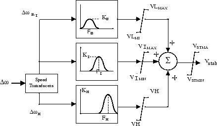
Each of the three bands is made of a differential bandpass filter, a gain, and a limiter (see the figure called Conceptual Representation). The outputs of the three bands are summed and passed through a final limiter producing the stabilizer output Vstab. This signal then modulates the set point of the generator voltage regulator so as to improve the damping of the electromechanical oscillations.
To ensure robust damping, the MB-PSS should include a moderate phase advance at all frequencies of interest to compensate for the inherent lag between the field excitation and the electrical torque induced by the MB-PSS action.
Conceptual Representation

Internal Specifications

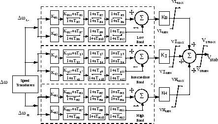
The MB-PSS is represented by the IEEE® St. 421.5 PSS 4B type model [2], illustrated in the figure called Internal Specifications, with built-in speed transducers whose parameters are fixed according to manufacturer's specifications.
Generally, only a few of the lead-lag blocks in this figure should be used in a given PSS application. Two different approaches are available to configure the settings in order to facilitate the tuning process:
Simplified settings:
Only the first lead-lag block of each frequency band is used to tune the Multiband Power System Stabilizer block. The differential filters are assumed to be symmetrical bandpass filters respectively tuned at the center frequency FL, FI, and FH. The peak magnitude of the frequency responses (see the figure called Conceptual Representation) can be adjusted independently through the three gains KL, KI, and KH. Only six parameters are therefore required for a simplified tuning of the MB-PSS.
Detailed settings:
The designer is free to use all the flexibility built into the MB-PSS structure to achieve nontrivial controller schemes and to tackle even the most constrained problem (for example, multi-unit plant including an intermachine mode, in addition to a local mode and multiple interarea modes). In this case, all the time constants and gains appearing in the figure called Internal Specifications have to be specified in the dialog box.
Ports
Input
Output
Parameters
References
[1] Grondin, R., I. Kamwa, L. Soulieres, J. Potvin, and R. Champagne, “An approach to PSS design for transient stability improvement through supplementary damping of the common low frequency,” IEEE Transactions on Power Systems, 8(3), August 1993, pp. 954-963.
[2] IEEE recommended practice for excitation system models for power system stability studies: IEEE St. 421.5-2002(Section 9).
Extended Capabilities
Version History
Introduced before R2006a