Permanent Magnet Synchronous Machine
(To be removed) Three-phase permanent magnet synchronous machine with sinusoidal or trapezoidal back electromotive force, or five-phase permanent magnet synchronous machine with sinusoidal back electromotive force
The Specialized Power Systems library will be removed in R2026a. Use the Simscape™ Electrical™ blocks and functions instead. For more information on updating your models, see Upgrade Specialized Power System Models to use Simscape Electrical Blocks.
Libraries:
Simscape /
Electrical /
Specialized Power Systems /
Electrical Machines
Description
The Permanent Magnet Synchronous Machine block implements a three-phase or a five-phase permanent magnet synchronous machine. The stator windings are connected in wye to an internal neutral point.
The three-phase machine can have a sinusoidal or trapezoidal back EMF waveform. The rotor can be round or salient-pole for the sinusoidal machine. The rotor is round when the machine is trapezoidal. Preset models are available for the sinusoidal back EMF machine.
The five-phase machine has a sinusoidal back EMF waveform and round rotor.
The Permanent Magnet Synchronous Machine block operates in either generator or motor mode. The mode of operation is dictated by the sign of the mechanical torque (positive for motor mode, negative for generator mode). The electrical and mechanical parts of the machine are each represented by a second-order state-space model.
The sinusoidal model assumes that the flux established by the permanent magnets in the stator is sinusoidal, which implies that the electromotive forces are sinusoidal.
The trapezoidal model assumes that the winding distribution and flux established by the permanent magnets produce three trapezoidal back EMF waveforms.
Three-Phase Sinusoidal Model Electrical System
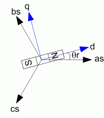
These equations are expressed in the rotor reference frame (qd frame). All quantities in the rotor reference frame are referred to the stator.
Lq, Ld | q-axis and d-axis inductances |
R | Resistance of the stator windings |
iq, id | q-axis and d-axis currents |
vq, vd | q-axis and d-axis voltages |
ωm | Angular velocity of the rotor |
λ | Amplitude of the flux induced by the permanent magnets of the rotor in the stator phases |
p | Number of pole pairs |
Te | Electromagnetic torque |
The Lq and Ld inductances represent the relation between the phase inductance and the rotor position due to the saliency of the rotor. For example, the inductance measured between phase A and B (when phase C is left open) is given by:
where Θe represents the electrical angle.
The next figure shows the variation of the phase-to-phase inductance in function of the electrical angle of the rotor.

For a round rotor, there is no variation in the phase inductance:
For a salient round rotor, the dq inductances are given by:
Five-Phase Sinusoidal Model Electrical System
These equations are expressed in the rotor reference frame using an extended Park transformation (q1d1 and q2d2 frame). All quantities in the rotor reference frame are referred to the stator.
L | Armature inductance |
R | Resistance of the stator windings |
iq1, id1 | q1-axis and d1-axis currents |
vq1, vd1 | q1-axis and d1-axis voltages |
iq2, id2 | q2-axis and d2-axis currents |
vq2, vd2 | q2-axis and d2-axis voltages |
ωm | Angular velocity of the rotor |
λ | Amplitude of the flux induced by the permanent magnets of the rotor in the stator phases |
p | Number of pole pairs |
Te | Electromagnetic torque |
Three-Phase Trapezoidal Model Electrical System
These equations are expressed in the phase reference frame (abc frame). Note that the phase inductance Ls is assumed to be constant and does not vary with the rotor position.
Ls | Inductance of the stator windings |
R | Resistance of the stator windings |
ia, ib, ic | a, b and c phase currents |
Φa', Φb', Φc' | a, b and c phase electromotive forces, in per-unit value to the amplitude of the flux λ |
vab, vbc | ab and bc phase to phase voltages |
ωm | Angular velocity of the rotor |
λ | Amplitude of the flux induced by the permanent magnets of the rotor in the stator phases |
p | Number of pole pairs |
Te | Electromagnetic torque |
The electromotive force Φ' is represented by:

Mechanical System
J | Combined inertia of rotor and load |
F | Combined viscous friction of rotor and load |
θ | Rotor angular position |
Tm | Shaft mechanical torque |
Tf | Shaft static friction torque |
ωm | Angular velocity of the rotor (mechanical speed) |
Limitations and Assumptions
When you use Permanent Magnet Synchronous Machine blocks in discrete systems, you might have to use a small parasitic resistive load, connected at the machine terminals, to avoid numerical oscillations. Large sample times require larger loads. The minimum resistive load is proportional to the sample time. Remember that with a 25 μs time step on a 60 Hz system, the minimum load is approximately 2.5% of the machine nominal power. For example, a 200 MVA permanent magnet synchronous machine in a power system discretized with a 50 μs sample time requires approximately 5% of resistive load, or 10 MW. If the sample time is reduced to 20 μs, a resistive load of 4 MW is sufficient.
The Permanent Magnet Synchronous Machine block assumes a linear magnetic circuit with no saturation of the stator and rotor iron. This assumption can be made because of the large air gap usually found in permanent magnet synchronous machines.
Ports
Input
Output
Conserving
Parameters
References
[1] Grenier, D., L.-A. Dessaint, O. Akhrif, Y. Bonnassieux, and B. LePioufle. “Experimental Nonlinear Torque Control of a Permanent Magnet Synchronous Motor Using Saliency.” IEEE® Transactions on Industrial Electronics, Vol. 44, No. 5, October 1997, pp. 680-687.
[2] Toliyat, H.A. “Analysis and Simulation of Multi-Phase Variable Speed Induction Motor Drives Under Asymmetrical Connections.” Applied Power Electronics Conference and Exposition, Vol. 2, March 1996, pp. 586-592.
[3] Beaudart, F., F. Labrique, E. Matagne, D. Telteux, and P. Alexandre. “Control under normal and fault tolerant operation of multiphase SMPM synchronous machines with mechanically and magnetically decoupled phases.” International Conference on Power Engineering, Energy and Electrical Drives, March 2009, pp. 461-466.
[4] Krause, P.C., O. Wasynczuk, and S.D. Sudhoff. Analysis of Electric Machinery and Drive Systems. IEEE Press, 2002.
Extended Capabilities
Version History
Introduced before R2006a


