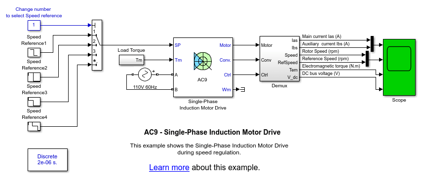
Single-Phase Induction Motor Drive
Implement single-phase induction motor drive

Description
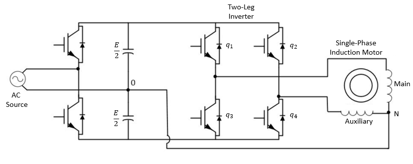
The Single-Phase Induction Motor Drive block models a vector-controlled single-phase machine drive. The drive configuration consists of a half-bridge rectifier, a divided DC bus with two filter capacitors, and a two-leg inverter that supplies the motor windings.
The single-phase induction machine (SPIM), without its startup and running capacitors, is treated as an asymmetric two-phase machine. The auxiliary and main windings are accessible and are in quadrature. This configuration provides good performances and operation in regenerating mode.
Equations
The single-phase induction motor is asymmetrical due to the unequal resistances and inductances of the main and auxiliary windings. To obtain the mathematical model of the motor with constant parameters (voltage, current, and flux), it is necessary to transform all the variables to the stationary reference frame (d-q) fixed to the stator.
Mathematical Model
This diagram shows the mathematical model of the machine.
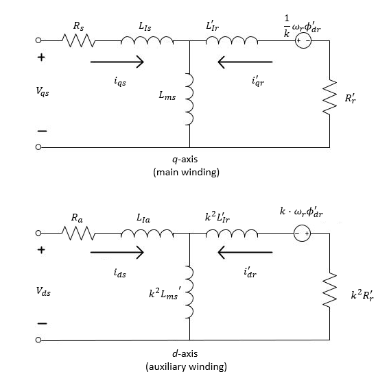
Na and Nm represent the number of auxiliary and main stator windings, respectively.
The equations that define the voltage for the model (in the stationary reference frame d-q) are:
and
where:
Vqs is the q-axis stator voltage.
Rs is the main stator resistance.
iqs is the q-axis stator current.
ϕqs is the q-axis stator flux linkage.
Vds is the d-axis stator voltage.
Ra is the auxiliary stator resistance.
ids is the d-axis stator current.
ϕds is the d-axis stator flux linkage.
R'r is the rotor winding resistance referred to the main stator winding.
i'qr is the q-axis rotor current referred to the main stator winding.
ϕ'qr is the q-axis rotor flux linkage referred to the main stator winding.
k is the turn ratio of Na to Nm.
ωr is the rotor electrical angular velocity.
i'dr is the d-axis rotor current referred to the main stator winding.
ϕ'dr is the d-axis rotor flux linkage referred to the main stator winding.
Na is the number of auxiliary stator windings.
Nm is the number of main stator windings.
The equations that define the flux for the model (in the stationary reference frame d-q) are:
where:
Lls is the leakage inductance of the main stator winding.
Lla is the leakage inductance of the auxiliary stator winding.
Lms is the magnetizing inductance of the main stator winding.
L'lr is the leakage inductance of the rotor winding referred to the main stator winding.
The electromagnetic torque expressed as a function of the rotor flux linkages and currents is
where:
Te is the electromagnetic torque.
P is the number of pole pairs.
Using the stator currents and rotor flux linkages as state-space variables for the SPIM model, the electromagnetic torque equation is
Using the next change of variable,
and
Therefore, the electromagnetic torque equation can be rewritten as
In the indirect rotor flux-oriented control, the d-axis of the reference frame is oriented along the rotor flux linkage vector ϕ'r, then
and
The electromagnetic torque results in
From here, the q-axis current component is
The resulting slip speed, ωs, is
From here, the d-axis current component is
where the e superscript indicates that the variable is referred to the synchronous reference frame.
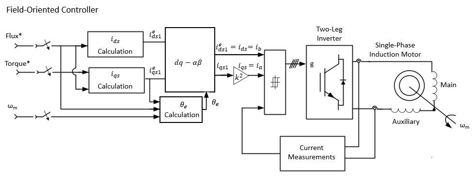
This block diagram shows field-oriented control.
This type of control selects the voltage vector from a switching table to control the power switches in the inverter to obtain the required stator flux and corresponding motor torque. From the motor equations in the stationary reference frame d-q, estimate the stator flux and the torque:
and
Assuming the approximation
and using the stator variables (flux linkages and currents) as state-space variables of the SPIM model, the electromagnetic torque is given by
Using the cross-product, the torque is
that is
where:
|ϕs| and |ϕr| are the magnitudes of the stator and rotor flux linkage space vectors, respectively.
δ is the angle between the space vectors.
A change in the relative movement of ϕs and ϕr (defined by the angle, δ) affects the motor instantaneous torque. If the voltage drop on the stator resistance is omitted, the stator flux linkage directly depends on the inverter output voltage.
The next diagram shows the available voltage vectors, which correspond to possible inverter states, and the four distinct sectors in the d-q plane for a two-leg inverter.

Selecting the appropriate inverter voltage vectors can directly change the magnitude of ϕs (flux control) and the rotating speed of ϕs (torque control) as shown in this diagram of sector 1.

This block diagram shows direct-torque control.
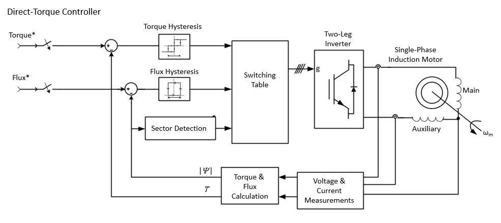
The estimated flux and torque are compared with the references using hysteresis control. The digitalized output variables and the stator flux position sector are used to select the appropriated voltage vector from the switching table. This table shows the appropriate voltage vector for the inverter where Hϕ and HTe are the output of the flux and torque hysteresis blocks
| Hϕ | HTe | Sector 1 | Sector 2 | Sector 3 | Sector 4 |
|---|---|---|---|---|---|
1 (Flux is up) | 1 (Torque is up) | V1 | V2 | V3 | V4 |
0 (Torque is down) | V4 | V1 | V2 | V3 | |
0 (Flux is down) | 1 (Torque is up) | V2 | V3 | V4 | V1 |
0 (Torque is down) | V3 | V4 | V1 | V2 |
Ports
Input
Output
Conserving
Parameters
Base sample time — Sample time
2e-06 (default)
Motor sample time.
Output bus mode — Block variant
Multiple outport buses (default) | Single outport buses
Configure the bus ports.
Dependencies
Selecting Multiple outport buses enables
the Conv and Ctrl
outports.
Use bus labels — Output signal labels
off (default) | on
Option to label bus signals.
Mechanical input — Block variant
Torque TM (default) | Mechanical rotational port
Configure the mechanical input and output ports. If you select
Torque TM, the output is the motor speed
according to this differential equation, which describes the mechanical
system dynamics:
where:
Te is the electromagnetic torque.
J is the inertia.
ωr is the angular velocity of the rotor.
F is the applied force.
Tm is the mechanical torque.
If you select Mechanical rotational port, the
connection port S acts as both the mechanical input and
output port. It allows a direct connection to the Simscape™ environment. The mechanical system of the motor is also
included in the drive and is based on the same differential equation.
Dependencies
Selecting Torque TM enables the
Tm and Wm ports. Selecting
Mechanical rotational port enables the
S port.
Motor
Electrical parameters > Nominal values
Power (VA) — Motor power
0.25*746 (default)
Motor nominal electrical power.
Voltage (Vrms) — Motor voltage
110 (default)
Motor nominal electrical voltage.
Frequency (Hz) — Frequency
60
Motor nominal electrical frequency.
Electrical parameters > Equivalent circuit values
To see the equivalent circuit for the unsymmetrical
SPIM, click Equivalent circuit.
Electrical parameters > Equivalent circuit values > Main winding stator
Resistance (ohm) — Resistance
2.02 (default)
Resistance of the stator main winding.
Leakage inductance (H) — Leakage inductance
7.4e-3 (default)
Motor main winding stator equivalent circuit leakage inductance.
Mutual inductance (H) — Mutual inductance
0.1772 (default)
Mutual inductance of the stator main winding.
Electrical parameters > Equivalent circuit values > Auxiliary winding stator
Resistance (ohm) — Resistance
7.14 (default)
Resistance of the stator auxiliary winding.
Leakage inductance (H) — Leakage inductance
8.5e-3 (default)
Leakage inductance of the stator auxiliary winding.
Mutual inductance (H) — Mutual inductance
1.18 (default)
Mutual inductance of the stator auxiliary winding.
Electrical parameters > Equivalent circuit values > Auxiliary winding rotor
Resistance (ohm) — Resistance
4.12 (default)
Resistance of the rotor main winding.
Leakage inductance (H) — Inductance
5.6e-3 (default)
Leakage inductance of the rotor main winding.
Mechanical parameters
Inertia (kg.m^2) — Inertia
0.0146 (default)
Motor inertia.
Friction factor (N.m.s) — Friction
0 (default)
Motor friction factor.
Pole pairs — Number of pole pairs
2 (default)
Number of motor pole pairs.
Initial speed w0 (%synchronous speed) — Initial speed
0 (default)
Motor Initial speed.
Converters and DC Bus
Rectifier > Snubbers
Resistance (ohm) — Resistance
10e3 (default)
Resistance of the rectifier snubbers. To eliminate the snubbers from
the model, specify inf.
Capacitance (F) — Capacitance
20e-9 (default)
Capacitance of the rectifier snubbers. To eliminate the snubbers from
the model, specify 0. For resistive snubbers, specify
inf.
Rectifier > Diodes
On-state resistance (ohm) — Resistance
1e-3 (default)
Internal resistance of the rectifier diodes when they are conducting.
Forward voltage (V) — Voltage
0.8 (default)
Voltage across the rectifier diodes when they are conducting.
DC Bus
Capacitance (F) — Capacitance
39e-4 (default)
Capacitance of the two capacitors in the DC bus
Braking Chopper
Resistance (ohm) — Resistance
8 (default)
The braking chopper resistance is used to avoid bus overvoltage during motor deceleration or when the load torque accelerates the motor.
Chopper Frequency (Hz) — Frequency
4000 (default)
Braking chopper frequency.
Activation voltage (V) — Voltage
310 (default)
The dynamic braking is activated when the bus voltage reaches the activation voltage value.
Shutdown voltage (V) — Voltage
300 (default)
The dynamic braking is shut down when the bus voltage reaches the shutdown value.
Inverter > Switches
On-state resistance (ohm) — Resistance
1e-3 (default)
Internal resistance of the inverter IGBTs when they are conducting.
Inverter > Switches > Forward voltages (V)
Main Device — Voltage
0 (default)
Forward voltage of the inverter IGBTs
Diode — Voltage
0 (default)
Forward voltage of the inverter diodes.
Inverter > Snubbers
Resistance (ohm) — Resistance
10e3 (default)
Resistance of the inverter snubbers. To eliminate the snubbers from
the inverter, specify inf.
Capacitance(F) — Capacitance
20e-9 (default)
Capacitance of the inverter snubbers. To eliminate the snubbers from
the model, specify 0. For resistive snubbers, specify
inf.
Controller
Regulation type — Type of regulation
Speed regulation (default) | Torque regulation
Type of regulation the controller is performing.
Dependencies
Selecting Speed regulation enables the
Speed cutoff frequency (Hz),
Speed ramps, and PI
regulator parameters.
Speed controller
Speed controller sampling time (s) — Sample time
7*20e-6 (default)
The sampling time must be a multiple of the simulation time step.
Speed cutoff frequency (Hz) — Frequency
1000 (default)
Cut-off frequency of the first-order low-pass filter of the speed controller.
Dependencies
Selecting Speed regulation for the
Regulation type parameter enables this
parameter.
Speed controller > Speed ramps (rpm/s)
Acceleration — Speed
1800 (default)
Maximum change of speed allowed during motor acceleration in rpm/s. An excessively large positive value can cause DC bus undervoltage.
Dependencies
Selecting Speed regulation for the
Regulation type parameter enables this
parameter.
Deceleration — Speed
-1800 (default)
Maximum change of speed allowed during motor deceleration in rpm/s. An excessively large negative value can cause DC bus overvoltage.
Dependencies
Selecting Speed regulation for the
Regulation type parameter enables this
parameter.
Speed controller > PI regulator
Proportional gain — Gain
1 (default)
Speed controller proportional gain.
Dependencies
Selecting Speed regulation for the
Regulation type parameter enables this
parameter.
Integral gain — Gain
0.001 (default)
Speed controller integral gain.
Dependencies
Selecting Speed regulation for the
Regulation type parameter enables this
parameter.
Speed controller > Torque output limits (N.m)
Negative — Gain
-4 (default)
Maximum negative demanded torque applied to the motor by the current controller in N.m.
Dependencies
Selecting Speed regulation for the
Regulation type parameter enables this
parameter.
Positive — Gain
4 (default)
Maximum positive demanded torque applied to the motor by the current controller in N.m.
Dependencies
Selecting Speed regulation for the
Regulation type parameter enables this
parameter.
Machine flux
Initial — Flux
0.3 (default)
Initial motor flux.
Nominal — Flux
0.3 (default)
Nominal motor flux.
Vector controller
To see schematics
for field-oriented control and direct-torque control, click
Schematic.
Controller type — Control model
FOC (default) | DTC (two-level hysteresis) | DTC (three-level hysteresis)
Type of control.
Dependencies
Selecting FOC enables the
Current controller hysteresis bandwidth (A)
parameter. Selecting DTC (two-level
hysteresis) or DTC (three-level
hysteresis) enables the Torque
controller hysteresis bandwidth (N-m) and
Flux controller hysteresis bandwidth (Wb)
parameters.
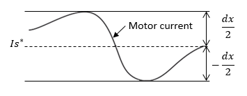
Current controller hysteresis bandwidth (A) — Hysteresis bandwidth
0.5 (default)
Total bandwidth in Current control mode, distributed symmetrically around the current set point. This figure illustrates a case where the current set point is Is* and the current hysteresis bandwidth is set to dx.
Dependencies
Selecting FOC for the
Controller type parameter enables this
parameter.
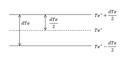
Torque controller hysteresis bandwidth (N-m) — Hysteresis bandwidth
0.1 (default)
Total bandwidth distributed symmetrically around the torque set point. This figure shows a case where the torque set point is Te* and the torque hysteresis bandwidth is set to dTe.
Dependencies
Selecting DTC (two-level hysteresis) or
DTC (three-level hysteresis) for the
Controller type parameter enables this
parameter.
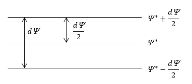
Torque controller hysteresis bandwidth (N-m) — Hysteresis bandwidth
0.1 (default)
Total bandwidth distributed symmetrically around the flux set point. This figure shows a case where the flux set point is Ψ* and the torque hysteresis bandwidth is set to dΨ.
Dependencies
Selecting DTC (two-level hysteresis) or
DTC (three-level hysteresis) for the
Controller type parameter enables this
parameter.
Flux controller hysteresis bandwidth (N-m) — Hysteresis bandwidth
0.002 (default)
Total bandwidth distributed symmetrically around the torque set point. This figure shows a case where the torque set point is Te* and the torque hysteresis bandwidth is set to dΨ.
Dependencies
Selecting DTC (two-level hysteresis) or
DTC (three-level hysteresis) for the
Controller type parameter enables this
parameter.
Maximum switching frequency (Hz) — Frequency
20000 (default)
Maximum inverter switching frequency.
Controller sampling time (s) — Sample time
20e-6 (default)
The sampling time must be a multiple of the simulation time step.
Version History
Introduced in R2017b
You can also select a web site from the following list:
Americas
- América Latina (Español)
- Canada (English)
- United States (English)
Europe
- Belgium (English)
- Denmark (English)
- Deutschland (Deutsch)
- España (Español)
- Finland (English)
- France (Français)
- Ireland (English)
- Italia (Italiano)
- Luxembourg (English)
- Netherlands (English)
- Norway (English)
- Österreich (Deutsch)
- Portugal (English)
- Sweden (English)
- Switzerland
- United Kingdom (English)