Surge Arrester
(To be removed) Implement metal-oxide surge arrester
The Specialized Power Systems library will be removed in R2026a. Use the Simscape™ Electrical™ blocks and functions instead. For more information on updating your models, see Upgrade Specialized Power System Models to use Simscape Electrical Blocks.
Library
Simscape / Electrical / Specialized Power Systems / Passives
Description
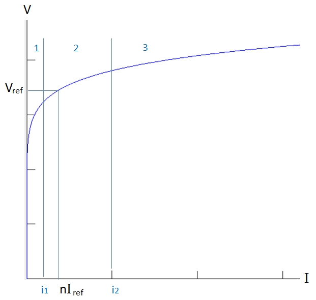
The Surge Arrester block implements a highly nonlinear resistor used to protect power equipment against overvoltages. For applications requiring high power dissipation, several columns of metal-oxide discs are connected in parallel inside the same porcelain housing. The nonlinear V-I characteristic of each column of the surge arrester is modeled by a combination of three exponential functions of the form
The protection voltage obtained with a single column is specified at a reference current (usually 500 A or 1 kA). Default parameters k and α given in the dialog box fit the average V-I characteristic provided by the main metal-oxide arrester manufacturers and they do not change with the protection voltage. The required protection voltage is obtained by adding discs of zinc oxide in series in each column.
This figure represents such a V-I characteristic.

Numbers 1, 2, and 3 identify the
three segments (or the exponential functions defining the model). The letter
n is the number of metal-oxide disc columns.
The transition currents from segment 1 to segment 2 and from segment 2 to segment 3 are equal to:
Where:
You may need to tune the parameters of the three segments to fit the V-I characteristic usually provided in the surge arrester datasheets.
Parameters
- Protection voltage Vref
The protection voltage of the Surge Arrester block, in peak voltage (V). Default is
500e+03.- Number of columns
The number of metal-oxide disc columns. The minimum is one. Default is
2.- Reference current per column Iref
The reference current of one column used to specify the protection voltage, in peak amperes (A). Default is
500.- Segment 1 characteristics
The k and α parameters of segment 1. Default is
[.955 50].- Segment 2 characteristics
The k and α parameters of segment 2. Default is
[1.0 25].- Segment 3 characteristics
The k and α characteristics of segment 3. Default is
[.9915 16.5].- Measurements
Select
Branch voltageto measure the voltage across the Surge Arrester block terminals.Select
Branch currentto measure the current flowing through the Surge Arrester block.Select
Branch voltage and currentto measure the surge arrester voltage and current.Default is
None.Place a Multimeter block in your model to display the selected measurements during the simulation. In the Available Measurements list box of the Multimeter block, the measurement is identified by a label followed by the block name.
Measurement
Label
Branch voltage
Ub:Branch current
Ib:
Advanced Tab
The Advanced tab of the block is not visible when you set the
Simulation type parameter of the powergui block to
Continuous, or when you select the Automatically handle
discrete solver parameter of the powergui block. The tab is visible
when you set the Simulation type parameter of the powergui
block to Discrete, and when the Automatically handle
discrete solver parameter of the powergui block is cleared.
- Break algebraic loop in discrete model
When selected, a delay is inserted at the output of the model. This delay eliminates the algebraic loop resulting from trapezoidal discretization methods and speeds up the simulation of the model. However, this delay introduces a one simulation step time delay in the model and can cause numerical oscillations if the sample time is too large. The algebraic loop is required in most cases to get an accurate solution.
When cleared (default), the discretization method of the model is specified by the Use robust solver in discrete model parameter.
- Use robust solver in discrete model
When cleared, Simulink® iterates to resolve the algebraic loop. Although this method produces correct results, it is not recommended because Simulink tends to slow down and may fail to converge (simulation stops) especially when the number of surge arresters is increased. Also, because of the Simulink algebraic loop constraint, this method cannot be used in real time. In R2018b and earlier releases, this method was used when the Break Algebraic loop in discrete saturation model parameter was cleared.
When selected, the robust solver iterates to resolve the algebraic loop. The maximum number of iterations is specified in the Preferences tab of the powergui block, in the Solver details for nonlinear elements section. For real time applications, you may need to limit the number of iterations. Usually, limiting the number of iterations to 2 produces acceptable results. The robust solver is the recommended method for discretizing the surge arrester model.
Limitations
The Surge Arrester block is modeled as a current source driven by the voltage appearing
across its terminals. Therefore, it cannot be connected in series with an inductor or another
current source. As the Surge Arrester block is highly nonlinear, a stiff integrator algorithm
must be used to simulate the circuit. de23t with default parameters usually
gives the best simulation speed. For continuous simulation, in order to avoid an algebraic loop,
the voltage applied to the nonlinear resistance is filtered by a first-order filter with a time
constant of 0.01 microseconds. This very fast time constant does not significantly affect the
result accuracy.
When you use the Surge Arrester block in a discrete system, see the Advanced tab.
Version History
Introduced before R2006a