FEM-Parameterized Synchronous Machine
Libraries:
Simscape /
Electrical /
Electromechanical /
Synchronous
Description
The FEM-Parameterized Synchronous Machine block models the electrical and mechanical characteristics of an externally excited synchronous machine or a hybrid excitation permanent magnet synchronous machine (PMSM) for which the magnetic flux linkage depends nonlinearly on the stator currents, field current, and rotor angle. Externally excited synchronous machines and PMSMs are also called synchronous AC motors and doubly-excited synchronous motors, respectively.
Use this block to model an externally excited electric motor or a machine that has a rotor field winding. This block captures detailed behavior like saturation effects and cogging torques by importing finite-element-derived lookup tables from a motor design tool. You can also model a hybrid excitation machine where the permanent magnets and the field winding generate the rotor flux.
The FEM-Parameterized Synchronous Machine block uses flux linkage that you must calculate using an external finite element (FE) tool. The block uses the A-phase flux linkage, which is a four-dimensional table that depends on the stator current magnitude, stator current phase advance, field winding current, and rotor angle. The block derives the field winding flux linkage by calculating the D-axis flux linkage from the A-phase, B-phase, and C-phase flux linkages and by subtracting the flux linkage when the field current is zero.
Equations
This equation defines the back electromotive force (EMF) of the stator:
where
eA, eB, and eC are the stator winding voltages.
ΨA, ΨB, and ΨC are the magnetic fluxes that link each stator winding.
L0 is the value of the Stator zero-sequence inductance, L0 parameter.
i0 is the zero-sequence current.
P is the Park transform.
To keep the table dimension small, this block does not tabulate the stator flux
linkages with the zero-sequence current. The block then adds the zero-sequence
dynamics with a separate term. If you set the Winding type
parameter to Wye-wound and do not enable the
Expose neutral port parameter, then the zero-sequence
dynamics are zero.
This equation defines the back EMF for the field winding of the rotor:
where:
Ψf is the field winding flux linkage. These equations define the field winding flux linkage:
ef is the field winding voltage.
Ψd, Ψq, and Ψ0 are the d-axis, q-axis, and zero-sequence fluxes, respectively.
ΨA(I,B,θ,if), ΨB(I,B,θ,if), and ΨC(I,B,θ,if) are the A-phase, B-phase, and C-phase flux linkages, respectively, tabulated with respect to I, B, θ, and if.
I is the stator peak current magnitude.
B is the stator current advance angle.
θ is the rotor angle.
Ψf (I,B,θ,if) is the field winding flux linkage tabulated with respect to I, B, θ, and if.
P is the Park transform, which depends on the option you choose for the Park’s convention for tabulated data parameter.
Note
The Park transform option of the Park’s convention for tabulated data parameter must match the version of the Park transform that you use in the FE tool to generate the flux linkage data.
Q leads D, rotor angle measured from A-phase to
						D-axis
Simscape™ Electrical™ motor and machine blocks use this convention internally and convert all other options to this format.
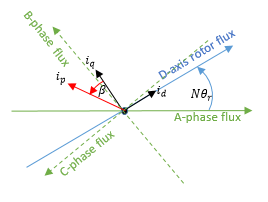
N is the value of the Number of pole pairs parameter.
θr is the rotor angle.
id and iq are the D-axis and Q-axis currents, respectively.
ip is the current magnitude and is equal to .
β is the current advance angle and is equal to .
The corresponding Park transform is
where ia, ib, and ic are the A-phase, B-phase, and C-phase currents, respectively.
Q leads D, rotor angle measured from A-phase to
						Q-axis
N is the value of the Number of pole pairs parameter.
θr is the rotor angle.
id and iq are the D-axis and Q-axis currents, respectively.
ip is the current magnitude and is equal to .
β is the current advance angle and is equal to .
The corresponding Park transform is
where ia, ib, and ic are the A-phase, B-phase, and C-phase currents, respectively.
D leads Q, rotor angle measured from A-phase to
						D-axis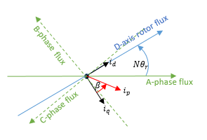
N is the value of the Number of pole pairs parameter.
θr is the rotor angle.
id and iq are the D-axis and Q-axis currents, respectively.
ip is the current magnitude and is equal to .
β is the current advance angle and is equal to .
The corresponding Park transform is
where ia, ib, and ic are the A-phase, B-phase, and C-phase currents, respectively.
D leads Q, rotor angle measured from A-phase to
						Q-axis
N is the value of the Number of pole pairs parameter.
θr is the rotor angle.
id and iq are the D-axis and Q-axis currents, respectively.
ip is the current magnitude and is equal to .
β is the current advance angle and is equal to .
The corresponding Park transform is
where ia, ib, and ic are the A-phase, B-phase, and C-phase currents, respectively.
Calculating Iron Losses
The FEM-Parameterized Synchronous Machine block models iron losses by using the Steinmetz equation. The Steinmetz equation scales for different motor speeds or electrical frequencies, so the block requires iron loss data only as a function of motor currents.
The block tabulates the iron losses coefficients with the Peak current magnitude vector, I, Current advance angle vector, B, and Field current vector, If parameters:
where:
f is the electrical frequency, in Hz.
khr(Ip,β,If) is the Rotor hysteresis loss coefficient, k_hr(I,B,If) parameter value.
kJr(Ip,β,If) is the Rotor eddy current loss coefficient, k_Jr(I,B,If) parameter value.
ker(Ip,β,If) is the Rotor excess current loss coefficient, k_er(I,B,If) parameter value.
khs(Ip,β,If) is the Stator hysteresis loss coefficient, k_hs(I,B,If) parameter value.
kJs(Ip,β,If) is the Stator eddy current loss coefficient, k_Js(I,B,If) parameter value.
kes(Ip,β,If) is the Stator excess current loss coefficient, k_es(I,B,If) parameter value.
Modeling Thermal Effects
You can expose thermal ports to model the effects of losses that convert power to heat. To expose the thermal ports, in the Thermal Ports section, enable the Model thermal effects parameter.
For more information about using thermal ports in actuator blocks, see Simulating Thermal Effects in Rotational and Translational Actuators.
Variables
To set the priority and initial target values for the block variables before simulation, use the Initial Targets section in the block dialog box or Property Inspector. For more information, see Set Priority and Initial Target for Block Variables.
Nominal values provide a way to specify the expected magnitude of a variable in a model. Using system scaling based on nominal values increases the simulation robustness. You can specify nominal values using different sources, including the Nominal Values section in the block dialog box or Property Inspector. For more information, see System Scaling by Nominal Values.
Examples
Assumptions and Limitations
If you model a hybrid-excitation machine, the block does not modulate the permanent magnet flux linkage with temperature.
