Piezo Linear Actuator
Force-speed characteristics of linear piezoelectric traveling wave motor
Libraries:
Simscape /
Electrical /
Electromechanical /
Mechatronic Actuators
Description
The Piezo Linear Actuator block represents the force-speed characteristics of a linear piezoelectric traveling wave motor. The block represents the force-speed relationship of the motor at a level that is suitable for system-level modeling. To simulate the motor, the block uses the following models:
Mass and Friction Model for Unpowered Motor
The motor is unpowered when the physical signal input v is zero. This corresponds to applying zero RMS volts to the motor. In this scenario, the block models the motor using the following elements:
A mass whose value is the Plunger mass parameter value.
A friction whose characteristics you specify using the parameter values in the Motor-Off Friction tab.
The block uses a Simscape™ Translational Friction block to model the friction component. For detailed information about the friction model, see the Translational Friction block reference page.
Resonant Circuit Model for Powered Motor
When the motor is active, Piezo Linear Actuator block represents the motor characteristics using the following equivalent circuit model.
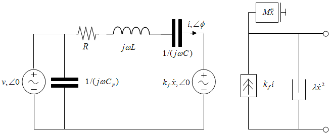
In the preceding figure:
The AC voltage source represents the block's physical signal input of frequency f and magnitude v.
The resistor R provides the main electrical and mechanical damping term.
The inductor L represents the rotor vibration inertia.
The capacitor C represents the piezo crystal stiffness.
The capacitor Cp represents the phase capacitance. This is the electrical capacitance associated with each of the two motor phases.
The force constant kf relates the RMS current i to the resulting mechanical force.
The quadratic mechanical damping term, , shapes the force-speed curve predominantly at speeds close to maximum RPM. is the linear speed.
The term represents the plunger inertia.
At model initialization, the block calculates the model parameters R, L, C, kt and λ to ensure that the steady-state force-speed curve matches the values for the following user-specified parameters:
Rated force
Rated speed
No-load maximum speed
Maximum (stall) force
These parameter values are defined for the Rated RMS voltage and Motor natural frequency (or rated frequency) parameter values.
The quadratic mechanical damping term produces a quadratic force-speed curve. Piezoelectric motors force-speed curves can typically be approximated more accurately using a quadratic function than a linear one because the force-speed gradient becomes steeper as the motor approaches the maximum speed.
If the plunger mass M is not specified on the datasheet, you can select a value that provides a good match to the quoted response time. The response time is often defined as the time for the rotor to reach maximum speed when starting from rest, under no-load conditions.
The quality factor that you specify using the Resonance quality factor parameter relates to the equivalent circuit model parameters as follows:
This term is not usually provided on a datasheet. You can calculate its value by matching the sensitivity of force to driving frequency.
To reverse the motor direction of operation, make the physical signal input v negative.
Assumptions and Limitations
When the motor is powered, the model is valid only between zero and maximum speed, for the following reasons:
Datasheets do not provide information for operation outside of normal range.
Piezoelectric motors are not designed to operate in the powered braking and generating regions.
The block behaves as follows outside the valid operating region:
Below zero speed, the model maintains a constant force with a zero speed value. The zero speed value is the Maximum (stall) force parameter value if the RMS input voltage equals the Rated RMS voltage parameter value, and the frequency input equals the Motor natural frequency parameter value.
Above maximum speed, the model produces the negative force predicted by the equivalent circuit model, but limits the absolute value of the force to the zero-speed maximum force.
The force-speed characteristics are most representative when operating the model close to the rated voltage and resonant frequency.
Ports
Input
Output
Conserving
Parameters
Extended Capabilities
Version History
Introduced in R2009a