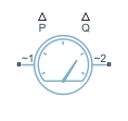
Power Sensor (Three-Phase)
Three-phase ideal active and reactive power sensor
Libraries:
Simscape /
Electrical /
Sensors & Transducers
Description
The Power Sensor (Three-Phase) block implements an ideal sensor for active and reactive power measurement in balanced or unbalanced three-phase branches.
For balanced branches, the block returns the correct value of the active and reactive power at all time instants. This is the preferred option for a load-flow analysis.
For unbalanced branches, to estimate the magnitude and phase, the block measures the phasors of the three voltages and currents independently by using a one-moving-period Fourier transform. For this reason, the output magnitude and phase are zero during the first period.
Unbalanced Branches Equations
The equivalent balanced phase voltage, current, and apparent power are:
where
VabRMS, VbcRMS, and VcaRMS are the three phase-to-phase RMS voltages.
IaRMS, IbRMS, and IcRMS are the RMS currents that flow through each of the three branches.
ρ is the ratio of neutral conductor resistance over phase conductor resistance, specified by the Neutral conductor resistance divided by phase conductor resistance parameter.
InRMS is the RMS neutral current.
The active power is then defined by:
where:
VaRMS, VbRMS, and VcRMS are the voltages of phase a, b, and c respectively.
φVa, φVb, and φVc are the phase shifts of the a-phase, b-phase, and c-phase voltages.
φIa, φIb, and φIc are the phase shifts of the a-phase, b-phase, and c-phase currents.
To compute the reactive power, the block first calculates its absolute value and then finds the sign by looking at the sign of the phase shift:
where φ = φV* - φI*. The * symbol denotes the central phase in the [-π,π] range.
Load-Flow Analysis
If the block is in a network that is compatible with the frequency-time simulation mode, you can perform a load-flow analysis on the network. A load-flow analysis provides steady-state values that you can use to initialize a machine.
For more information, see Perform a Load-Flow Analysis Using Simscape Electrical and Frequency and Time Simulation Mode.
Ports
Conserving
Output
Parameters
References
[1] Willems, Jacques, "The IEEE standard 1459: What and why?", 2010 IEEE International Conference on Applied Measurements for Power Systems, Proceedings: 41-46.
Extended Capabilities
Version History
Introduced in R2020b
