Main Content

Buck Converter

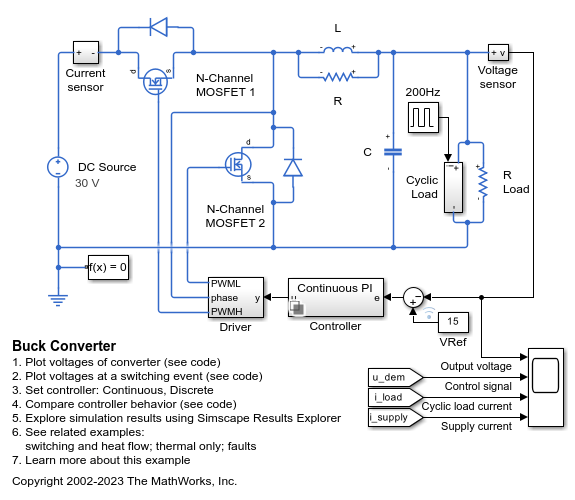
This example shows how to model a switching power supply that converts a 30V DC supply into a regulated 15V DC supply. Use this model to size the inductance L and the smoothing capacitor C and to design the feedback controller. Select between continuous and discrete controllers to explore the impact of the discretization.

Modeling the switching devices as MOSFETs rather than ideal switches ensures that the model correctly represents the on-resistances of the device. The model also captures the switch-on/switch-off timing of the devices, this timing depends primarily on the gate capacitance values and the PWM driver output resistance.

For an abstracted version of this model that uses ideal switching to give faster simulation times, see the Buck Converter with Thermal Dynamics example. You can use the model in this example to determine the on-resistance values required for the ideal switches, and the timing offsets if necessary. To simulate more complext power converters, use the ideal switching approach of the BuckThermalDynamics model.

The Workspace variables T_junction1 and T_junction2 define the temperatures at which the model simulates the two MOSFETs. The BuckThermalDynamics and BuckThermal models determine these temperatures.

Model

Simulation Results from Simscape Logging

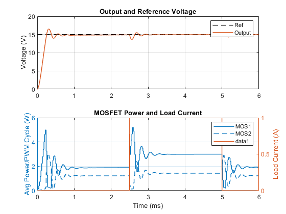
This plot shows a comparison between the output voltage and the reference voltage. It also shows the changing load current and the dissipated power of the two MOSFETs averaged over the PWM cycle.

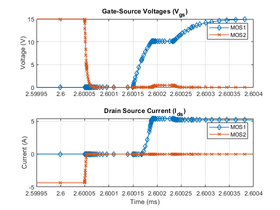
This plot shows the switch-on/switch off timing of the two MOSFETs and the drain-source current.

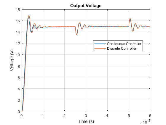
These plots show the behavior of the different implementations of the PI controller.