转换器(低功率)
利用这些示例了解如何为低功率应用(低于 48 V)的转换器(例如 DC-DC 转换器、斩波转换器、降压转换器和升压转换器)进行建模。
精选示例
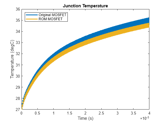
Improve Simulation Speed of Power Electronics Systems with Reduced Order Modeling
Enhance the model simulation speed of an electro-thermal DC-DC step-down converter by converting a high-fidelity switch to a reduced order model (ROM) switch. This conversion enables faster design iterations and analysis.
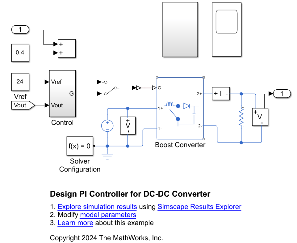
Design PI Controller for DC-DC Converter
Design a PI controller for a DC-DC converter using classical control theory. Alternatively, you can use Steady State Manager, Model Linearizer, Frequency Response Estimator, or PID tuner apps to streamline the design.
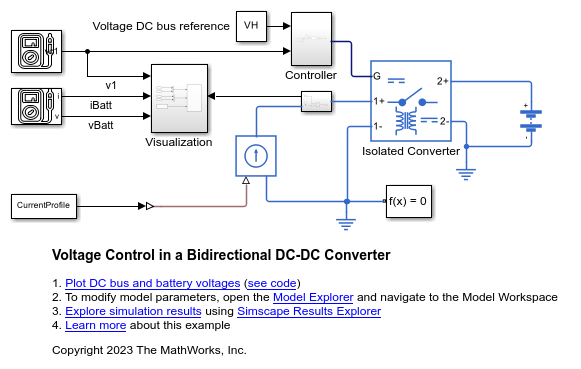
Voltage Control in a Bidirectional DC-DC Converter
Control the voltage of a DC bus connected to a load, a current source, and a battery with an isolated converter.
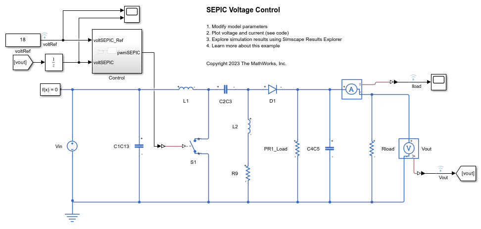
SEPIC Voltage Control
Control the output voltage of a single-ended primary-inductor converter (SEPIC). The SEPIC is a form of DC-DC converter designed to deliver a regulated positive output voltage, regardless of whether the input voltage is higher, equal to, or lower than the intended output voltage. The Control subsystem adjusts the duty cycle of the semiconductor switch to regulate the output of the SEPIC. To adjust the duty cycle, the Control subsystem uses a PI-based control algorithm. The input voltage is constant throughout the simulation. A resistor provides the load for the system. The total simulation time is 0.1 seconds.

Deploy SEPIC Model to FPGA
Deploy a single-ended primary-inductor converter (SEPIC) model to a Speedgoat® IO334-325K Simulink®-programmable I/O module and then run the model in real-time at a sample step size of 1 microsecond. The parts of the model that you deploy to CPU, run at 50 microseconds.
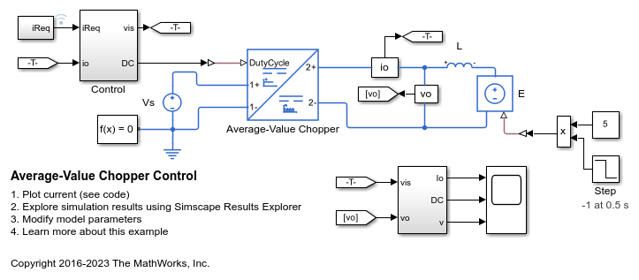
Average-Value Chopper Control
Control a four-quadrant chopper. The Control subsystem implements a simple PI-based control algorithm for controlling the output current. An average-value Chopper model is used to speed up the simulation. The simulation uses both positive and negative references. The total simulation time (t) is 1 s. At t = 0.5 s, the polarity of the load DC source E changes.
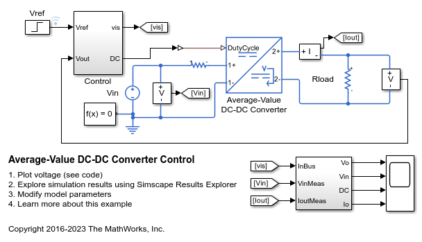
Average-Value DC-DC Converter Control
Control the output voltage of a buck-boost converter. To adjust the duty cycle, the Control subsystem uses a PI-based control algorithm. An average-value DC-DC converter model is used to speed up the simulation. The input voltage and the system load are held constant throughout the simulation. The total simulation time (t) is 0.25 s. At t = 0.15 s, the voltage reference changes and the system switches from buck mode to boost mode.
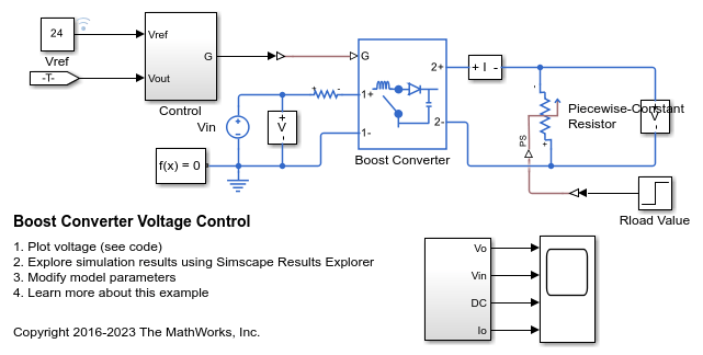
升压转换器电压控制
此示例展示了如何控制升压转换器的输出电压。为了调整占空比,Control 子系统使用基于 PI 的控制算法。在整个仿真过程中,输入电压被视为恒定的。一个可变电阻器为系统提供负载。总仿真时间 (t) 为 0.25 秒。在 t = 0.15 秒时,负载发生变化。
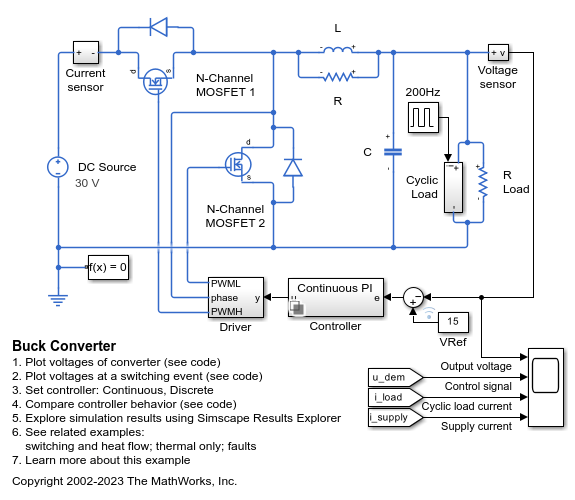
降压转换器
此示例展示了如何对将 30V DC 电源转换为 15V DC 稳压电源的开关电源进行建模。使用此模型确定电感 L 和平滑电容器 C 的大小,并设计反馈控制器。在连续控制器和离散控制器之间进行选择,以探索离散化的影响。
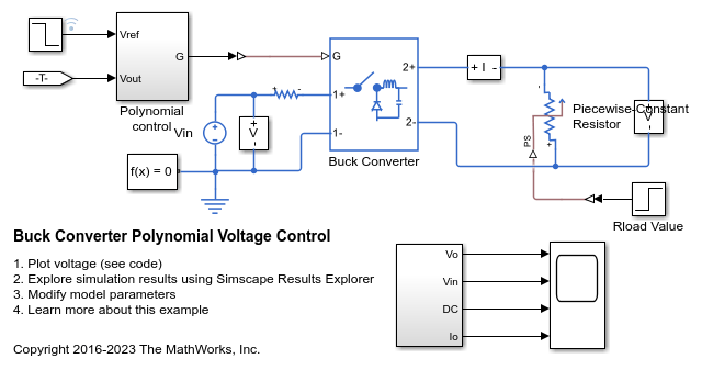
Buck Converter Polynomial Voltage Control
Control the output voltage of a buck converter using a polynomial RST controller. The RST controller adjusts the duty cycle. The input voltage is considered constant throughout the simulation. A variable resistor provides the load for the system. The total simulation time (t) is 0.25 seconds. At t = 0.15 seconds, the load is changed. At t = 0.2 seconds, the voltage reference is changed from 6V to 4V.
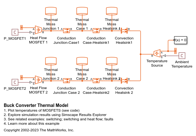
Buck Converter Thermal Model
Models the thermal dynamics of MOSFETs in a synchronous buck converter. It matches the structure of the Buck Converter with Thermal Dynamics model. Omitting the electrical switching dynamics allows the simulation to take much larger time steps, dramatically reducing the amount of time it takes for the simulation to calculate steady-state temperatures for the MOSFETS.
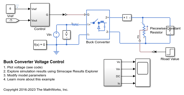
降压转换器电压控制
此示例展示了如何控制降压转换器的输出电压。为了调整占空比,Control 子系统使用基于 PI 的控制算法。在整个仿真过程中,输入电压被视为恒定的。一个可变电阻器为系统提供负载。总仿真时间 (t) 为 0.25 秒。在 t = 0.15 秒时,负载发生变化。
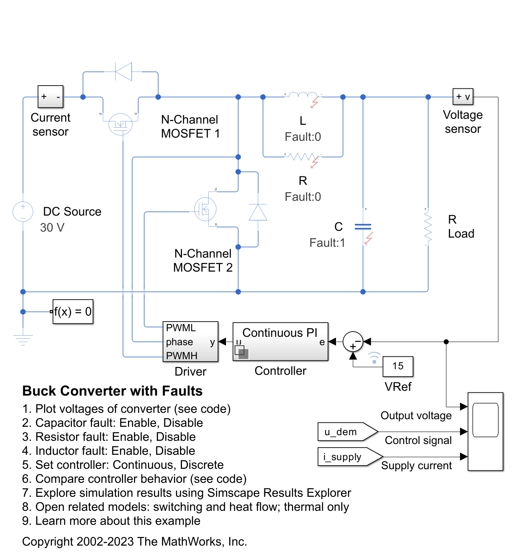
Buck Converter with Faults
Model and assess the impact of component tolerances and fault events on the operation of a switching power supply. The R, L, and C components all have tolerances, operational limits, and faults defined. The faults can be enabled within the block dialog or using MATLAB® Commands. The capacitor fault is already enabled to cut in at 1.5e-3 seconds.
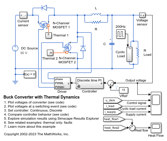
Buck Converter with Thermal Dynamics
Model a switching power supply that converts a 30V DC supply into a regulated 15V DC supply. The model can be used to both size the inductance L and smoothing capacitor C, as well as to design the feedback controller. By selecting between continuous and discrete controllers, the impact of discretization can be explored. Modeling the switching devices as MOSFETs rather than ideal switches ensures that device on-resistances are correctly represented. The model also captures the switch-on/switch-off timing of the devices, this depending primarily on the gate capacitance values and the PWM driver output resistance.
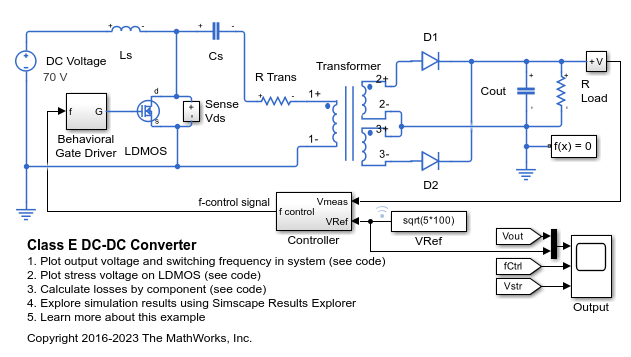
Class E DC-DC Converter
A Class E power converter with frequency control. A simple integral control is implemented in Simulink® in the Controller block, and is designed to deliver 100W into a 5ohm load. The switch is an LDMOS, high-voltage transistor with a nonlinear capacitance model, and R Trans is the equivalent series resistance of the transformer. The Output scope shows the drain-source voltage for evaluation of the voltage stress on the switch. Note that, due to the nonlinear output capacitance of the transistor, the peak voltage stress is higher than would be expected if the output capacitance were constant. In addition, the scope also shows the frequency control signal, the output voltage, and the reference value for the output voltage. This model can be used to calculate the output power information from components in the circuit.
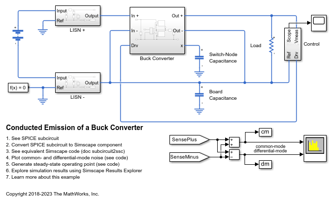
Conducted Emission of a Buck Converter
A buck converter configured for a measurement of common- and differential-mode noise on the source. In order to simulate the common-mode noise, the capacitive coupling between the circuit and a reference plane must be included in the model. In this circuit, the capacitance between the switching node (between the high- and low-side transistors) and the reference plane is also included.

DC-DC LLC Converter
A DC-DC LLC power converter with frequency control. The Controller block implements a simple integral control in Simulink®. This integral control achieves a nominal output voltage, specified in the variable Vout_nominal. The Output scope shows the frequency control signal, the output voltage, and the reference value for the output voltage. During startup, the reference value ramps up to its desired setpoint. The design of the LLC powertrain is computed automatically using the first harmonic approximation.

First and Fourth Quadrant Chopper Control
Control a two-quadrant chopper. The two-quadrant chopper operates in the first and fourth quadrants, allowing positive and negative output voltage. The Control subsystem implements a simple PI-based control algorithm for controlling the output current. The total simulation time (t) is 0.5 seconds. At t = 0.25 seconds, the polarity of the load DC source E is changed.
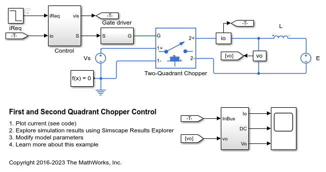
First and Second Quadrant Chopper Control
Control a two-quadrant chopper. The two-quadrant chopper operates in the first and second quadrants, allowing positive and negative output current. The Control subsystem implements a simple PI-based control algorithm for controlling the output current. The load of the system is considered constant throughout the simulation.
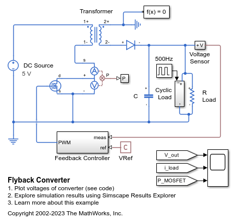
Flyback Converter
How a flyback converter can step-up a 5V DC source into a 15V DC regulated supply. The voltage is increased by creating a time-varying voltage across a transformer primary. The transformer steps up the voltage which is then rectified back to DC by the diode. Closed-loop control over the output voltage is effected by controlling the switching frequency on the primary side.
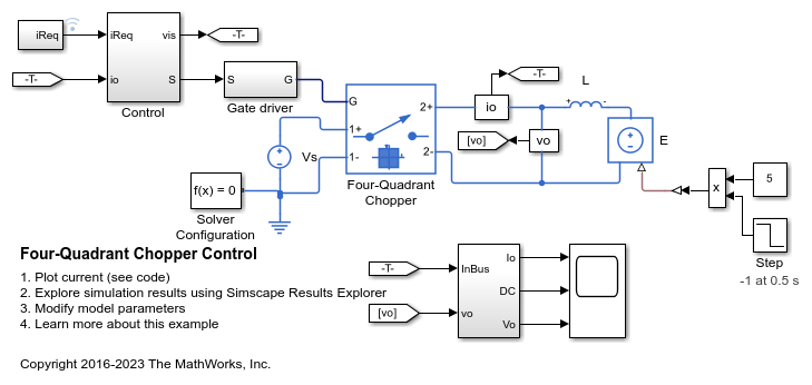
Four-Quadrant Chopper Control
Control a four-quadrant chopper. The Control subsystem implements a simple PI-based control algorithm for controlling the output current. The simulation uses both positive and negative references. The total simulation time (t) is 1 second. At t = 0.5 seconds, the polarity of the load DC source E is changed.
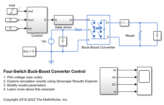
Four-Switch Buck-Boost Converter Control
Control the output voltage of a four-switch buck-boost converter. To adjust the duty cycle, the Control subsystem uses a PI-based control algorithm. In both the boost and buck modes, one switch controls the duty cycle, one is operated inversely and the other two are kept in fix positions. The input voltage and the system load are considered constant throughout the simulation. The total simulation time (t) is 0.25 seconds. At t = 0.15 seconds, the voltage reference changes and the system switches from buck mode to boost mode.
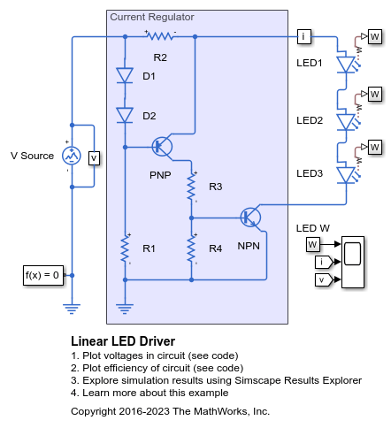
Linear LED Driver
A LED driver based on a linear current regulator. The scope shows the light and current output and the supply voltage. The output comes into regulation for a supply voltage greater than about 12V.

Linearize DC-DC Converter Model
Linearize a model of a DC-DC converter using averaged switching or an average-value converter.
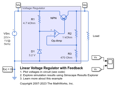
Linear Voltage Regulator with Feedback
A simple voltage regulator circuit constructed from discrete components. A fluctuating supply is modeled as 20V DC plus a 1V sinusoidal variation. The zener diode D1 sets the non-inverting input of the op-amp to 3.2V, and hence as the op-amp has a large gain, the op-amp inverting input and output are also at 3.2V. Hence the regulator voltage output is regulated to be 3.2*(1000+470)/470=10V. The NPN bipolar transistor is required to provide higher currents than is possible from a typical op-amp. The model can be used to check circuit operation, and to support selection of components to achieve the desired voltage regulation.
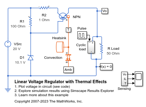
Linear Voltage Regulator with Thermal Effects
A low-cost voltage regulator circuit whose performance depends on both load current and temperature. Bias resistor R1 ensures that the voltage at the transistor base is close to the rated zener voltage. The regulator output voltage is also approximately at this voltage, the base-emitter voltage being a few tenths of a volt. The precise base-emitter voltage depends on the transistor working point (which in turn depends on the load) and also the temperature. Resistor R2 only serves to provide some protection in the event of a transient output short circuit.
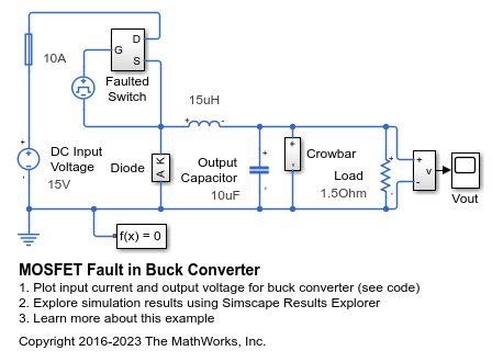
MOSFET Fault in Buck Converter
How a fault may be applied to a MOSFET in a power converter in order to explore the operation of protection circuitry. After the MOSFET becomes faulted, the crowbar circuitry is activated in order to clamp the output voltage across the load and eventually to cause the fuse to blow.

One-Quadrant Chopper Control
Control a one-quadrant chopper. The Control subsystem implements a simple PI-based control algorithm for controlling the output current.
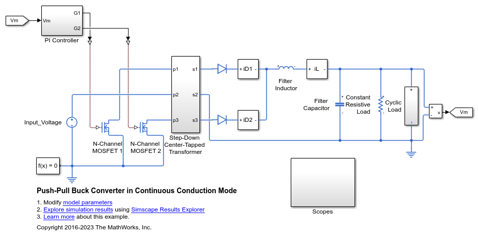
Push-Pull Buck Converter in Continuous Conduction Mode
Control the output voltage of a push-pull buck converter. The current flowing through the inductor is never zero. The DC-DC converter therefore operates in continuous conduction mode (CCM). To convert and maintain the nominal output voltage, the PI Controller subsystem uses a simple integral control. During startup, the reference voltage ramps up to the desired output voltage.
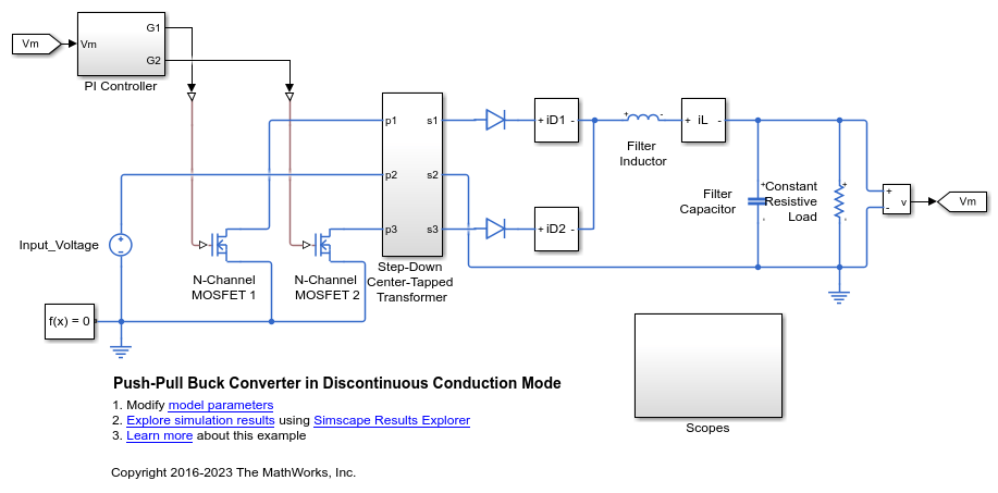
Push-Pull Buck Converter in Discontinuous Conduction Mode
Control the output voltage of a push-pull buck converter. The current flowing through the inductor reaches zero during the switch off cycle of the MOSFETs and therefore the DC-DC converter operates in Discontinuous Conduction Mode (DCM). This mode of conduction is mostly used for low-power applications. To convert and maintain the input DC voltage as a nominal output voltage, the PI Controller subsystem uses a simple integral control. During startup, the reference voltage is ramped up to the desired output voltage.
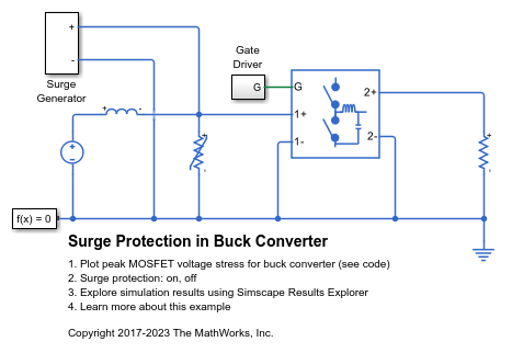
Surge Protection in Buck Converter
How a varistor may be applied to a buck converter in order to protect the switching MOSFETs from over-voltages due to a differential surge.
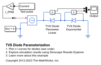
TVS Diode Parameterization
How to parameterize the Simscape™ Electrical™ diode to represent a Transient Voltage Suppression (TVS) diode. This example is for a TVS diode suited to protecting automotive electronics from voltage transients associated with turning off inductive loads. To view the data extracted from the datasheet, on the Modeling tab, in the Setup section, click Model Settings > Model Properties. On the Callbacks tab, click PreLoadFcn.
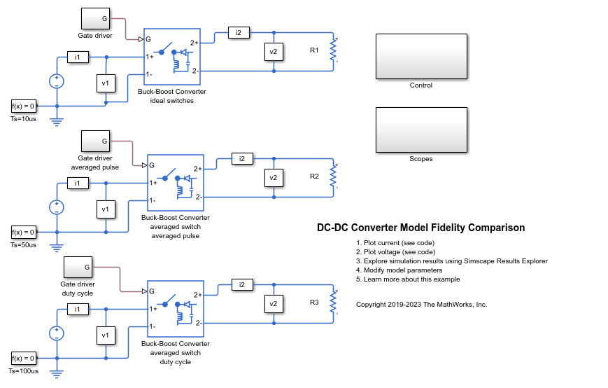
DC-DC Converter Model Fidelity Comparison
Use different levels of fidelity in DC-DC converters. The system contains three buck-boost converters. The top converter uses an ideal switch at a sample time of 10 us. To yield accurate results even though the model is under sampled at a sample time of 50 us, the middle converter uses an averaged switch with averaged pulse. To further increase the sample rate and to operate as an ideal averaged converter, the bottom converter uses an averaged switch and duty cycle instead of gate pulse. The Control subsystem contains a PWM generator. The Scopes subsystem contains Scope blocks that allow you to see the simulation results.

Chopper Model Fidelity Comparison
Use different levels of fidelity in chopper converters. You change the level of fidelity by changing the values for the Fidelity level, Switching device, and Integral protection diode parameters of the Four-Quadrant Chopper block. You also change the inputs to the G port. Using a higher level of fidelity improves the accuracy of the results but it also slows down simulation.
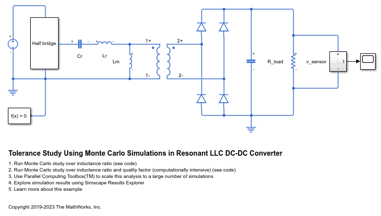
Tolerance Study Using Monte Carlo Simulations in Resonant LLC DC-DC Converter
Use Simscape™ Electrical™ to perform a Monte Carlo analysis to optimize the design of an LLC resonant DC-DC converter when some of its components have tolerances.
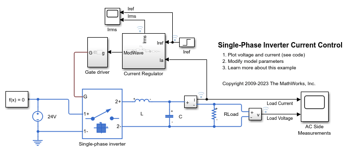
单相逆变器电流控制
此示例展示了如何控制单相逆变器系统中的电流。该单相逆变器采用由调制波形供电的平均开关。此示例适用于在专用实时仿真器上进行实时评估。
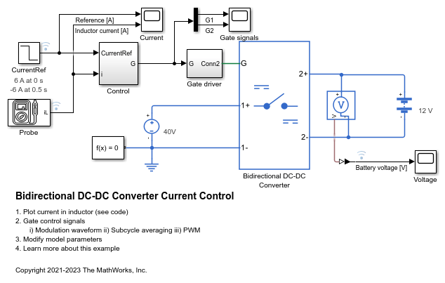
双向 DC-DC 转换器电流控制
此示例展示了如何控制双向 DC-DC 转换器的电感器电流。为了调整占空比,Control 子系统使用基于 PI 的控制算法。双向 DC-DC 转换器使用平均开关。为了实现不同的保真度级别,您可以使用调制波形、平均栅极脉冲或栅极脉冲。

Two-Phase DC-DC Converter Current Control
Control the current of a two-phase interleaved bidirectional DC-DC converter. The two-phase converter comprises two Bidirectional DC-DC Converter with ideal IGBTs. To adjust the duty cycle, the Control subsystem uses a PI-based control algorithm. To reduce the ripple at the output port of the converter, the two phases are switched with the same duty ratio but with a relative phase shift of 180 degrees. The Scopes subsystem contains scopes that allow you to see the simulation results.
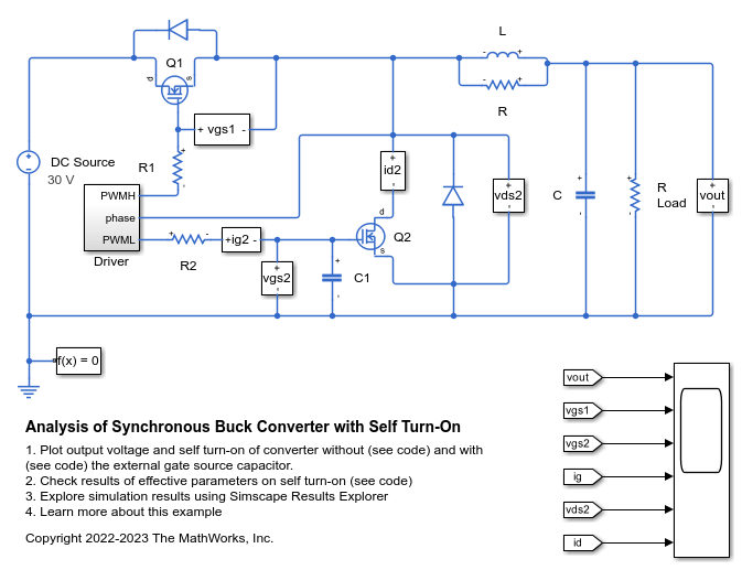
Analysis of Synchronous Buck Converter with Self Turn-On
How the MOSFET parameters affect the self turn-on mechanism and how you can prevent it.
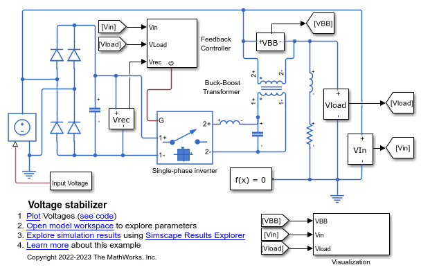
Power Converter Voltage Stabilizer
A voltage stabilizer circuit. It uses a full-wave rectifier, a single-wave inverter, and a buck-boost transformer to achieve voltage regulation.