Conducted Emission of a Buck Converter
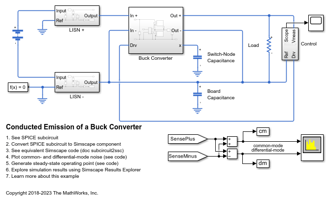
This example shows a buck converter configured for a measurement of common- and differential-mode noise on the source. In order to simulate the common-mode noise, the capacitive coupling between the circuit and a reference plane must be included in the model. In this circuit, the capacitance between the switching node (between the high- and low-side transistors) and the reference plane is also included.
Ideal line impedance stabilization networks (LISNs) are placed between each terminal of the power supply and the inputs of the buck converter in order to provide a standard impedance and measurement port for the common- and differential-mode noise.
In order to obtain the noise measurement under steady-state conditions, a steady-state operating point has been saved and is used as the starting point for the noise simulation.
Convert MOSFET subcircuit to Simscape component
In this example, you will convert this MOSFET subcircuit to a Simscape™ component. To open the SPICE netlist, in the MATLAB® command window, enter edit BuckConductedEmissionSPICEMOSFET.cir.
Run this command to convert the SPICE subcircuit of the BuckConductedEmissionSPICEMOSFET.cir model to a Simscape component and place the generated files in the newly created directory called +BuckConductedEmissionSimscapeMOSFET:
Netlist converted. Review Simscape component files and make
manual edits for any unsupported items before building the
Simscape library located at:
+BuckConductedEmissionSimscapeMOSFET.
Model

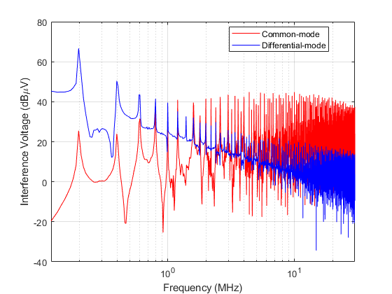
The plot below shows the common- and differential-mode noise for a buck converter operating at a switching frequency of 200kHz.
