Class E DC-DC Converter
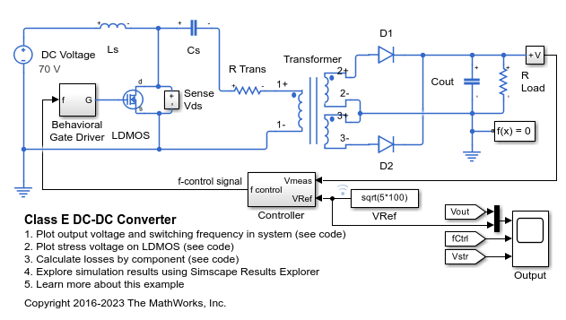
This example shows a Class E power converter with frequency control. A simple integral control is implemented in Simulink® in the Controller block, and is designed to deliver 100W into a 5ohm load. The switch is an LDMOS, high-voltage transistor with a nonlinear capacitance model, and R Trans is the equivalent series resistance of the transformer. The Output scope shows the drain-source voltage for evaluation of the voltage stress on the switch. Note that, due to the nonlinear output capacitance of the transistor, the peak voltage stress is higher than would be expected if the output capacitance were constant. In addition, the scope also shows the frequency control signal, the output voltage, and the reference value for the output voltage. This model can be used to calculate the output power information from components in the circuit.
Model

Simulation Results from Simscape Logging
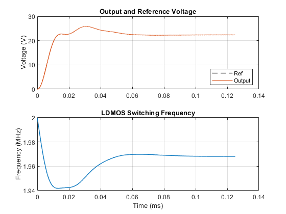
The plot below shows the output voltage as compared to the reference voltage. It also shows the change in switching frequency which is how the control system attempts to make the output track the reference voltage.

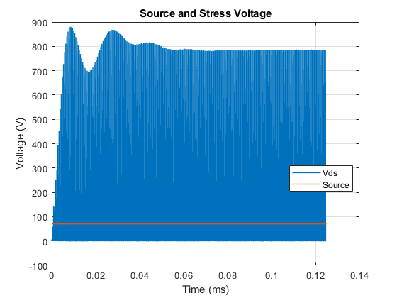
The plot below shows the voltage stress on the LDMOS as compared to the source voltage. This architecture for a power converter requires a significantly higher voltage stress than architectures with two semiconductor devices.

The table below shows the power dissipated by individual components in the ClassEDCDCConverter model. These totals were calculated from simulation results using logged Simscape™ variables and the losses calculation utility ee_getPowerLossSummary. The total output power in the load, as well as the losses are shown.
Averaging power data from 0.0001s to 0.000125s.
Total efficiency = 90.4771% for an output power of 99.8799W.
Loss contributions are shown below.

              LoggingNode              Power
    _______________________________    _____

    {'ClassEDCDCConverter.LDMOS'  }    3.49
    {'ClassEDCDCConverter.R_Trans'}    2.81
    {'ClassEDCDCConverter.D2'     }    1.91
    {'ClassEDCDCConverter.D1'     }    1.79
    {'ClassEDCDCConverter.Cs'     }    0.26
    {'ClassEDCDCConverter.Ls'     }    0.25
    {'ClassEDCDCConverter.Cout'   }       0
See Also
N-Channel LDMOS FET | Three-Winding Mutual Inductor | ee_getPowerLossSummary
Topics
- Calculate Power Losses for One Block
- Calculate Dissipated Power Losses for the Entire Simulation Time
- Calculate Dissipated Power Losses for a Specific Time Period
- Calculate Efficiency for Circuit
- Calculate Efficiency and Power-Loss Contributions
- Calculate Efficiency of Circuit for Specific Time Period
- Calculate Voltage Derivatives for Block
- Calculate Voltage Derivatives by Block for Model
- Calculate Voltage Derivatives in Specific Time Period
- Calculate Maximum Voltage Derivatives by Block for the Whole Model
- Calculate Maximum Voltage Derivatives for One Block
- Calculate Maximum Voltage Derivatives for a Specific Time Period