Linear Electric Actuator with Control
This example shows a detailed implementation model of a controlled linear actuator. The actuator consists of a DC motor driving a worm gear which in turn drives a lead screw to produce linear motion. The model includes quantization effects of the Hall-effect sensor and the implementation of the control in analog electronics. There are multiple variant subsystems in this model that have models at varying levels of fidelity.
The speed control and current control models are implemented using pure Simulink® blocks. This permits us to easily specify the control algorithm and identify the requirements for an analog circuit implementation, which is shown in another variant.
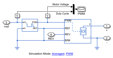
The motor drive circuit model is implemented in an abstract circuit which can simulate in two different simulation modes. In average mode, the voltage applied to the motor varies continuously between the maximum and minimum values depending upon the voltages at its input pins. In PWM mode, a PWM voltage is applied to the motor and its duty cycle depends on the voltage applied at its input pins. The motor circuit is also implemented using semiconductor devices. This enables exploration of individual switching events.
Model

Speed Controller Subsystem
The circuit shown below implements a PI controller with a filter using Simscape™ Electrical™ components. This is enabled when the Circuit variant is selected within the Speed and Current Control subsystem.

Abstract Motor Driver Circuit Subsystem
The blocks below are an abstract model of a motor driver circuit. The Controlled PWM Voltage block generates a PWM signal based on the voltages at its +ref and -ref ports. The H-Bridge block represents an H-bridge circuit commonly used to drive electric motors. These blocks can be configured to run in average mode or PWM mode.

Simulation Results from Simscape Logging - Abstract Model
The plot below shows how the motor speed tracks a reference input. The actual speed of the shaft and the speed determined by the shaft encoder are shown, indicating that the signal that the control system sees is not a perfect measurement of the shaft speed. The system response to a disturbance torque at 3 seconds is shown.

Circuit Subsystem
The circuit shown below is an H-bridge circuit implemented using Simscape Electrical components. It is enabled when the Circuit variant of the Motor Driver variant subsystem is selected.

MOSFET Subsystem
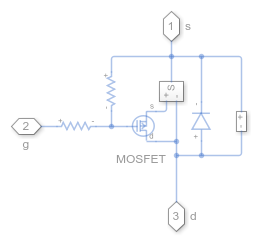
The circuit below is one of the four legs of the H-bridge. The MOSFET semiconductor and other components control the flow of current through the leg of the H-bridge.

Simulation Results from Simscape Logging - Detailed Model
The plot below shows a single switching event during a simulation using the detailed model of the H-bridge. The spike in MOSFET power is due to the fact that for a brief period of time, both MOSFETs on the same side of the motor are conducting, creating a short circuit.

See Also
DC Motor | Optocoupler | P-Channel MOSFET | H-Bridge | Controlled PWM Voltage