机器人和机电
利用这些示例了解如何控制电机、比较电机的特性并开发电动作动器。
精选示例
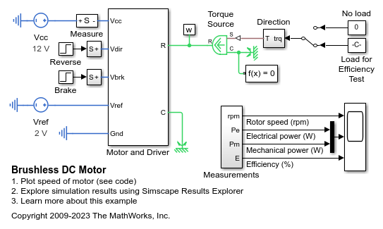
Brushless DC Motor
How a system-level model of a brushless DC motor (i.e. a servomotor) can be constructed and parameterized based on datasheet information. The motor and driver are modeled as a single masked subsystem. If viewing the model in Simulink®, select the Motor and driver block, and type Ctrl+U to look under the mask and see the model structure.
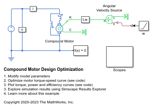
Compound Motor Design Optimization
Find design parameters that optimize a compound motor torque-speed curve to match the desired curve.
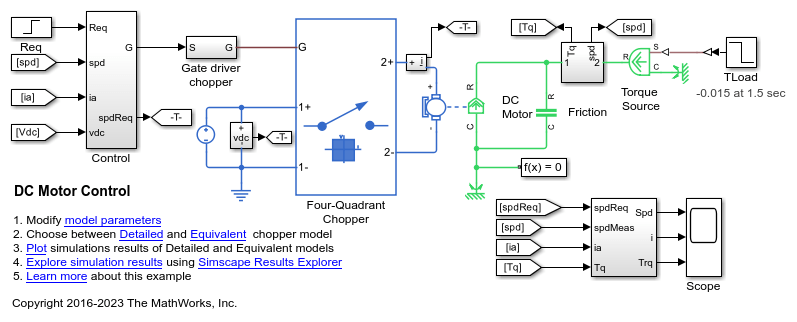
DC 电机控制
此示例展示了 DC 电机的级联速度控制结构。采用 PWM 控制的四象限斩波器为该 DC 电机供电。Control 子系统包括外层转速控制环、内层电流控制环和 PWM 生成模块。总仿真时间 (t) 为 4 秒。在 t = 1.5 秒时,负载转矩增加。在 t = 2.5 秒时,参考转速从 1000 rpm 变为 2000 rpm。

DC 电机控制(超前-滞后)
此示例展示了 DC 电机的超前-滞后转速控制结构。采用 PWM 控制的四象限斩波器为该 DC 电机供电。Control 子系统包括超前-滞后控制器、常量增益和 PWM 生成模块。总仿真时间 (t) 为 4 秒。在 t = 1.5 秒时,负载转矩增加。在 t = 2.5 秒时,参考转速从 1000 rpm 变为 2000 rpm。
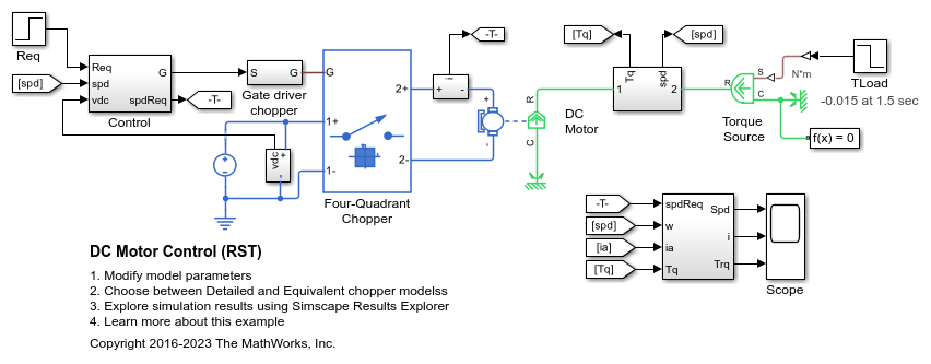
DC 电机控制 (RST)
此示例展示了 DC 电机的 RST 转速控制结构。采用 PWM 控制的四象限斩波器为该 DC 电机供电。Control 子系统包括控制时域为 30 的 RST 控制器和 PWM 生成模块。传感器测量转子转速,存在 5 毫秒的延迟。总仿真时间 (t) 为 4 秒。在 t = 1.5 秒时,负载转矩增加。在 t = 2.5 秒时,参考转速从 1000 rpm 变为 2000 rpm。
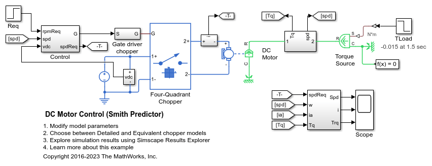
DC 电机控制(史密斯预估器)
此示例展示了 DC 电机的史密斯预估器转速控制结构。采用 PWM 控制的四象限斩波器为该 DC 电机供电。Control 子系统包括史密斯预估器控制器和 PWM 生成模块。传感器测量转子转速,存在 5 毫秒的延迟。总仿真时间 (t) 为 4 秒。在 t = 1.5 秒时,负载转矩增加。在 t = 2.5 秒时,参考转速从 1000 rpm 变为 2000 rpm。
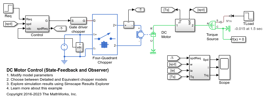
DC 电机控制(状态反馈和观测器)
此示例展示了 DC 电机的状态反馈转速控制结构。采用 PWM 控制的四象限斩波器为该 DC 电机供电。Control 子系统包括状态反馈控制环和 PWM 生成模块。状态向量包括测得的转子转速和使用观测器估计的 DC 电机电流。观测器和状态反馈控制器都是利用系统的状态空间模型通过极点配置合成的。总仿真时间 (t) 为 4 秒。在 t = 1.5 秒时,负载转矩增加。在 t = 2.5 秒时,参考转速从 1000 rpm 变为 2000 rpm。

Hybrid Linear Actuator
A hybrid actuator consisting of a DC motor plus lead screw in series with a piezoelectric stack. The DC motor and lead screw combination supports large displacements (tens of millimeters), but is dynamically slow when tracking the reference demand x_ref. Conversely the piezoelectric stack only supports a maximum displacement of +-0.1mm, but has a very fast dynamic response. Combining the two actuator technologies creates a large stroke actuator with highly precise positioning.

Import Efficiency Map Data from Motor-CAD
Import efficiency map data from Motor-CAD to parameterize the Simscape™ Electrical™ Motor & Drive (System Level) block. This provides fast system-level simulation capability of a motor drive whilst still making accurate predictions about losses.

Linear Electric Actuator (Motor Model)
How to develop a model of an uncontrolled linear actuator using datasheet parameter values. The actuator consists of a DC motor driving a 6.25:1 worm gear which in turn drives a 3mm lead screw to produce linear motion. Manufacturer data for the actuator defines the no-load linear speed (26mm/s), rated load (1000N), rated-load linear speed (19mm/s), and maximum current (5A). The maximum static force is 4000N and the rated voltage is 24V DC.

Linear Electric Actuator with Control
A detailed implementation model of a controlled linear actuator. The actuator consists of a DC motor driving a worm gear which in turn drives a lead screw to produce linear motion. The model includes quantization effects of the Hall-effect sensor and the implementation of the control in analog electronics. There are multiple variant subsystems in this model that have models at varying levels of fidelity.

Model a Motor Drive with Multiple Intermittent Torque Limits
Model a motor drive with multiple intermittent over-torque limits by using Simscape™ Electrical™.
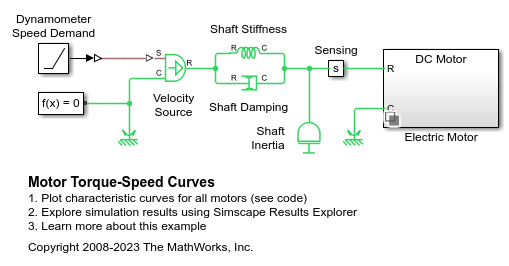
电机转矩-转速曲线
此示例对比了五种不同电机类型的转矩-转速特性。要选择电机类型,请右键点击 Electric Motor 模块,然后从上下文菜单中选择模块参数(子系统)。在新窗口中,使用标签模式活动选择项参数指定所需的电机。所有电机的尺寸大致按照相同的额定机械功率设计。

使用 PWM 电压源和 H 桥驱动器控制 DC 电机
此示例展示了如何使用 Controlled PWM Voltage 和 H-Bridge 模块来控制 DC 电机。DC Motor 模块在 2500 rpm 转速下提供 10 W 的机械功率,并且在 DC 电源电压为 12 V 时以 4000 rpm 的空载转速运行。因此,如果将 PWM 参考电压设置为其最大值 5 V,电机将以 4000 rpm 的转速运行。如果将 PWM 参考电压设置为 2.5 V,电机将以约 2000 rpm 的转速运行。为了实现快速仿真,此示例将 Controlled PWM Voltage 模块和 H-Bridge 模块的仿真模式参数设置为 Averaged。要验证平均行为,请在 Controlled PWM Voltage 模块和 H-Bridge 模块中将 Simulation mode 参数都设置为 PWM。
Stepper Motor Averaged Mode
The Stepper Motor simulating in Stepping and Averaged simulation modes. The purpose of Averaged mode is faster simulation for any loads that do not cause slip. To avoid incorrect interpretation of results, the stepper motor has an approximate detection of slip which can be set to generate a warning or an error.
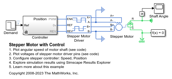
带控制的步进电机
此示例展示了如何使用 Stepper Motor 模块和 Stepper Motor Driver 模块对受控永磁步进电机进行建模。该模型有两个控制器选项:一个用于控制位置,一个用于控制转速。要更改控制器类型,请右键点击 Controller 子系统,选择变体 > 标签模式活动选择项,然后选择位置或转速。该步进电机的整步距为 1.8 度。在位置控制模式下,Ref 端口的输入是所需的步数。在转速控制模式下,Ref 端口的输入是所需的每秒步数。
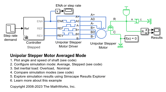
Unipolar Stepper Motor Averaged Mode
The Unipolar Stepper Motor simulating in Stepping and Averaged simulation modes. The purpose of Averaged mode is faster simulation for any loads that do not cause slip. To avoid incorrect interpretation of results, the stepper motor has an approximate detection of slip which can be set to generate a warning or an error.
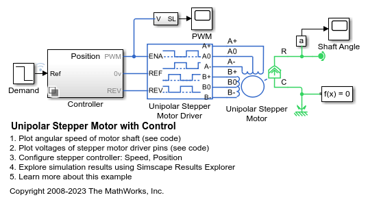
带控制的单极步进电机
此示例展示了如何使用 Unipolar Stepper Motor 模块和 Unipolar Stepper Motor Driver 模块对受控永磁步进电机进行建模。该模型有两个控制器选项:一个用于控制位置,一个用于控制转速。要更改控制器类型,请右键点击 Controller 子系统,选择变体 > 标签模式活动选择项,然后选择位置或转速。该步进电机的整步距为 1.8 度。在位置控制模式下,Ref 端口的输入是所需的步数。在转速控制模式下,Ref 端口的输入是所需的每秒步数。