带控制的步进电机
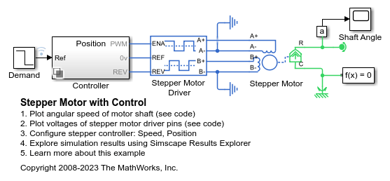
此示例展示了如何使用 Stepper Motor 模块和 Stepper Motor Driver 模块对受控永磁步进电机进行建模。该模型有两个控制器选项:一个用于控制位置,一个用于控制转速。要更改控制器类型,请右键点击 Controller 子系统,选择变体 > 标签模式活动选择项,然后选择位置或转速。该步进电机的整步距为 1.8 度。在位置控制模式下,Ref 端口的输入是所需的步数。在转速控制模式下,Ref 端口的输入是所需的每秒步数。
此模型适用于在系统层面研究步进电机的动态特性,并确定在驱动给定负载时步进角是否会失步。您可以使用该模型来调整步进控制器以提高步进性能。您还可以在现成的步进控制器模块上部分或全部实现该控制器。在微处理器(例如外围接口控制器 (PIC))上实现算法可以提供更大的灵活性,并且您可以使用微处理器来控制系统的其他部分。您可以在微处理器上实现部分 Stepper Motor Driver 模块,仅将功率放大器部分留在模拟电子电路中。
打开模型
查看位置控制测试的仿真结果
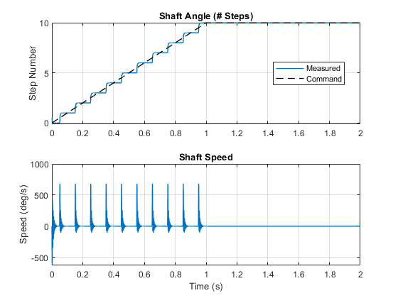
下图对使用位置控制器时的电机轴角度与指令信号进行了比较。位置控制算法接受位置命令作为步数,并将命令转换为控制步进电机驱动器的脉冲序列。当轴稳定在其指令位置时,角速度图上会出现峰值。
查看转速控制测试的仿真结果
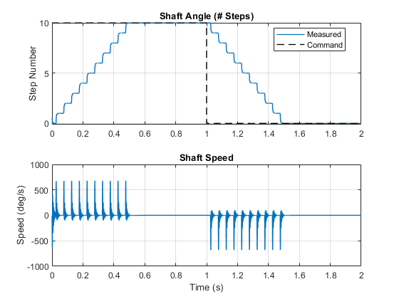
下图对使用转速控制器时的电机轴角度与指令信号进行了比较。转速控制算法接受转速命令作为每秒步数,并将命令转换为控制步进电机驱动器的脉冲序列。当轴稳定在其当前时间步时,角速度图上会出现峰值。
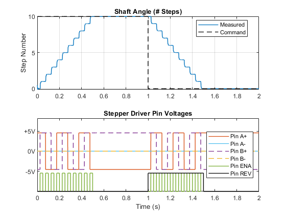
下图显示了步进电机驱动器上引脚的状态如何影响步进电机的运动。每当使能 (ENA) 信号上升到高于 Stepper Motor Driver 模块的使能阈值电压参数值时,驱动器都会启动一个步进动作。
另请参阅
Stepper Motor | Stepper Motor Driver