Battery Pack Thermal Management
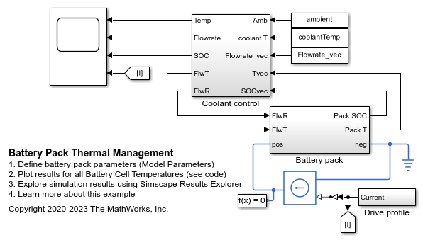
This example shows how to model an automotive battery pack for thermal management tasks. The battery pack consists of several battery modules, which are combinations of cells in series and parallel. Each battery cell is modeled using the Battery (Table-Based) Simscape™ Electrical™ block. In this example, the initial temperature and the state of charge are the same for all cells. Four battery modules, three similar and one differing from the other three, are connected in series to simulate a battery pack. The results in this example assume an initial ambient temperature equal to 25 degree Celsius. The Coolant Controls subsystem defines the logic used to determine the battery pack coolant flow rate.
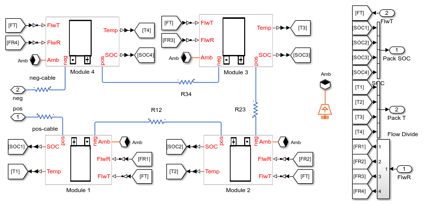
Model Overview
Parameters and Input Overview
To use this model to create a unique battery module, first specify the number of series- and parallel-connected cells. Then specify the cell type for all individual cells by choosing one of these options for the Choose cell type parameter of the Battery Module block:
PouchCanCompact cylindricalRegular cylindrical
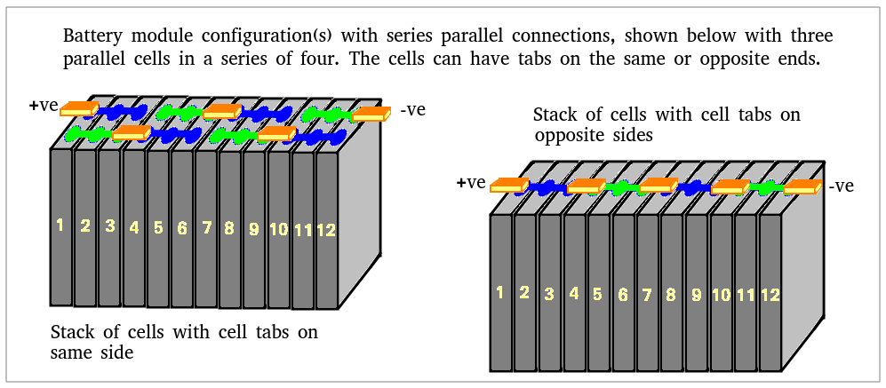
This example uses pouch-type cells. Module A,B and C consist of five series-connected and two parallel-connected cells. Module D consists of six series-connected and two parallel-connected cells.
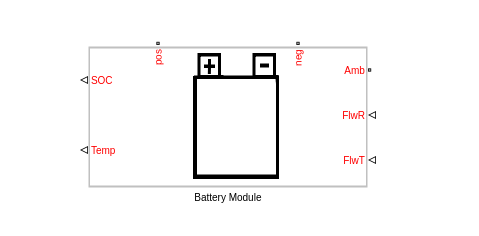
The two output ports, SOC and Temp, provide information regarding the state of charge and the temperature of each cell in the module. The thermal port, Amb, is used to define the ambient temperature in the simulation. The electrical ports, pos and neg, define the electrical positive and negative terminals, respectively. The two input ports, FlwR and FlwT, define the battery coolant flow rate control and inlet temperature into the module.
The figure below shows examples of battery cells in Pouch and Can configurations.
The figure below shows examples of battery cells in Compact cylindrical and Regular cylindrical configurations.

These are the parameters in the battery module:
Vector of temperatures, T - Temperatures at which the cell or module data for temperature-varying properties are tabulated, specified as a vector.
Single cell Ahr rating, baseline - Cell capacity at the temperatures defined in the Vector of temperatures, T parameter, specified as a vector.
Vector of state of charge values, SOC - Range of values between 0 and 1 at which the cell electrical parameters are defined, specified as a vector.
Vector of coolant flowrates, L - Coolant mass flow rate values at which a lookup table for cell cooling is defined. This parameter needs to cover multiple points in the flow range of interest. This parameter defines the size of the Effective rate of coolant heat transfer parameter and is specified as a vector.
No load voltage, V0 - Cell open-circuit potential values at different Vector of state of charge values, SOC and Vector of temperatures, T points, specified as a matrix.
Terminal resistance, R0 - Cell ohmic resistance values at different Vector of state of charge values, SOC and Vector of temperatures, T points, specified as a matrix.
Polarization resistance - Polarization resistance values at different Vector of state of charge values, SOC and Vector of temperatures, T points, specified as a matrix.
Time constant - Time constant at different Vector of state of charge values, SOC and Vector of temperatures, T points, specified as a matrix.
Cell thermal mass - Thermal mass of a single cell, specified as a scalar.
Cell thermal conductivity - Cell through-plane conductivity for pouch and can cells, or the radial conductivity for cylindrical cells, specified as a scalar.
Heat transfer coefficient to ambient - Heat transfer coefficient value, specified as a scalar.
Number of series connected cells Ns - Number of strings in series, specified as an integer.
Number of parallel connected cells Np - Number of parallel-cells in a string, specified as an integer.
Choose cell type - Type of cell, specified as either
Pouch,Can,Compact cylindrical, orRegular cylindrical.Cell height - Cell height, specified as a scalar.
Cell width - Cell width for
PouchandCancells, specified as a scalar.Cell thickness - Cell thickness for
PouchorCancells, specified as a scalar.Cell diameter - Cell diameter for
Compact cylindricalorRegular cylindrical, specified as a scalar.Number of cylindrical cells in a straight line - Number of cylindrical cells arranged in a straight line for packaging, specified as an integer.
Accessory total resistance - Resistance that combines all inline resistance in a module, specified as a scalar. This resistance is the sum of cell tab, busbar, cable and/or weld resistances, specified as a scalar.
Cell balancing - Cell balancing method, specified as either
noneorpassive. In this example, this parameter is set tonone.
Effective rate of coolant heat transfer from each cell - Estimate of the thermal resistance (W/K) of heat transfer from battery cells to coolant, specified as a 3-D matrix of scalar values. The 3-D matrix size depends on the Vector of temperatures, T, Vector of coolant flowrates, L and NsxNp parameters. The NsxNp parameter is the total number of cells in the module. The battery cooling is represented as a lookup table or 3-D matrix of size [T,L,Ns*Np] and the values are calculated using detailed 3-D methods such as computational fluid dynamics. The values of the matrix depend on the actual hardware design of the cooling system or cold plates in the module. The performance of the cold plate is controlled using input values FlwR and FlwT.
External heat - External heat input to each cell in a module due to a hot component placed near the module, specified as a vector.
Vector of initial cell temperature - Cell initial temperature, specified as a vector.
Vector of initial cell state of charge - Cell initial state of charge, specified as a vector.
Cell Ahr rating variation - Cell-to-cell variations in cell capacity at all Vector of temperatures, T points for each cell, specified as a vector of scalar values. If you set this array to 1, all cell capacity is the same. The array values for a cell are multiplied with the value specified in the Single cell Ahr rating, baseline parameter to calculate the actual capacity or the Ahr rating of the cell.
To define the battery coolant flow rate and temperature, specify these inputs:
FlwR - Value between 0 and 1, specified as a scalar. The FlwR input value is used to dynamically choose the right value of the flow rate during the simulations. The value of the FlwR input defines the actual flow rate in the module. In the Vector of coolant flowrates L parameter, FlwR equal to 0 means no flow, while FlwR equal to 1 means highest flow rate value.
FlwT - Positive or negative value that, when summed to the ambient temperature, equals the coolant inlet temperature. A value of +15 for the FlwT input and 273.15 K at the Amb port makes the coolant inlet temperature equal to 273.15 + 15 = 288.15K. A value of -15 for the FlwT input and 273.15 K at the Amb makes the coolant inlet temperature equal to 273.15 - 15 = 258.15 K
In this example, the battery pack consists of four modules connected in series. The first three modules are identical. The fourth module has a different number of cells, Ns4, and cooling efficiency, coolantQ4, defined in the BatteryThermalManagementInitialization.m file. Cables, modeled as resistors, connect the modules to each other. All modules have a different flow rate of coolant. The Flow Divide block in the Battery Pack subsystem determines the flow rate that reaches each battery module.
Coolant Control Subsystem Overview
The Coolant Control subsystem tracks the minimum and maximum temperatures in the battery pack. This subsystem calculates the flow rate based on the largest value between the difference in the maximum and the minimum cell temperatures in the pack, and the difference in the maximum temperature in the pack and the value at the Amb port. For a difference of 10 degrees Celsius or more, FlwR is set to 1, else it is linearly scaled till zero, when there is no temperature difference between the different cells and the battery pack temperature is very close the value set at the Amb port. In this example, the coolant inlet temperature, defined in the coolantTemp workspace variable in the BatteryThermalManagementInitialization.m file, is constant.

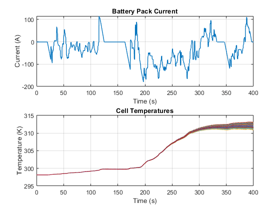
Simulation Results from Simscape Logging
This example simulates a 600 seconds drive profile. The flow rate increases along with the battery pack temperature, leading to a better cooling of the battery pack.