能源储存
利用这些示例了解如何通过电池和电容器储存能源。
精选示例
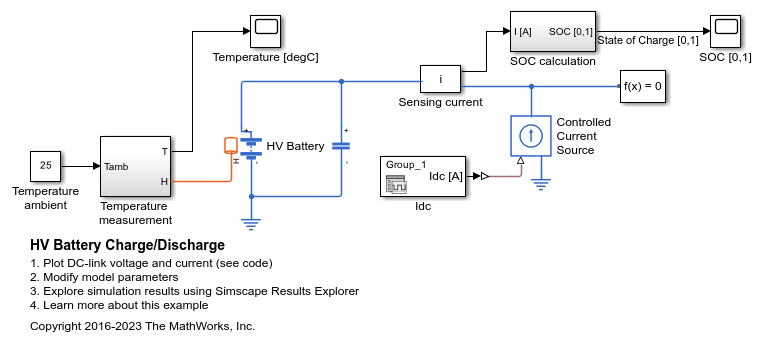
高压电池充放电
此示例展示了与混合动力电动汽车中所用高压电池类似的高压电池。该模型使用源自于动态驾驶循环的真实 DC 链路电流曲线。总仿真时间为 3600 秒。

Battery Pack Cell Balancing
Implement a passive cell balancing for a Lithium-ion battery pack. Cell-to-cell differences in the module create imbalance in cell state of charge and hence voltages. In this example, the balancing algorithm starts when the battery pack is idle and the difference in the cell state of charge is above a certain predefined value.
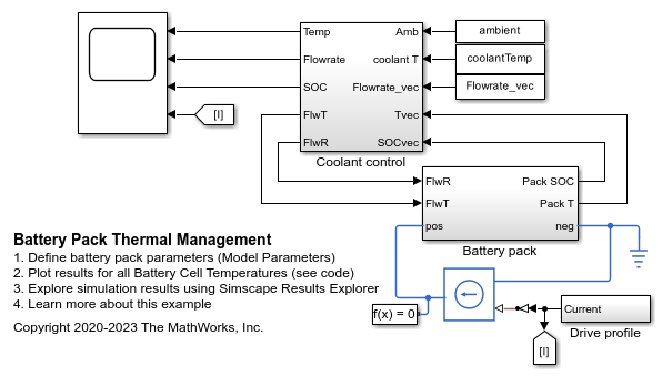
Battery Pack Thermal Management
Model an automotive battery pack for thermal management tasks. The battery pack consists of several battery modules, which are combinations of cells in series and parallel. Each battery cell is modeled using the Battery (Table-Based) Simscape™ Electrical™ block. In this example, the initial temperature and the state of charge are the same for all cells. Four battery modules, three similar and one differing from the other three, are connected in series to simulate a battery pack. The results in this example assume an initial ambient temperature equal to 25 degree Celsius. The Coolant Controls subsystem defines the logic used to determine the battery pack coolant flow rate.
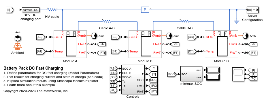
Battery Pack DC Fast Charging
Model an automotive battery pack for DC fast charging tasks. The battery pack consists of several battery modules, which are combinations of cells in series and parallel. Each battery cell is modeled using the Battery (Table-Based) Simscape Electrical block. In this example, the initial temperature and the state of charge are the same for all cells. The cell capacity varies according to the manufacturing tolerances or uncertainties. Three battery modules, two similar and one differing from the other two, are connected in series to simulate a battery pack. The results in this example assume an initial ambient temperature equal to zero degree Celsius. The Controls subsystem defines the logic to determine the battery pack charging time and current.
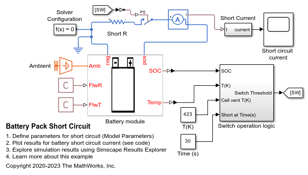
Battery Pack Short Circuit
Model a short-circuit in a lithium-ion battery module. The battery module consists of 30 cells with a string of three parallel cells connected in a series of ten strings. Each battery cell is modeled using the Battery (Table-Based) Simscape Electrical block. In this example, the initial temperature and the state of charge are the same for all cells. There is no coolant flow modeled in this example. The battery module is shorted with a 0.1mOhm resistor. There is an inrush current followed by cell quick discharge and heating up. Once the cell reaches the trigger temperature for thermal runaway and cell venting, the electrical circuit is disconnected to stop the electrical simulation.
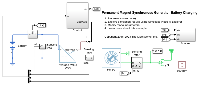
永磁同步发电机电池充电
此示例展示了如何使用永磁同步发电机 (PMSG) 为电池充电。使用理想角速度源来保持转子转速恒定。Control 子系统采用磁场定向控制来调节 PMSG 的转矩。转矩参考值根据 DC 链路电压获得。初始电池荷电状态为 25%。Scopes 子系统包含示波器,可用于查看仿真结果。
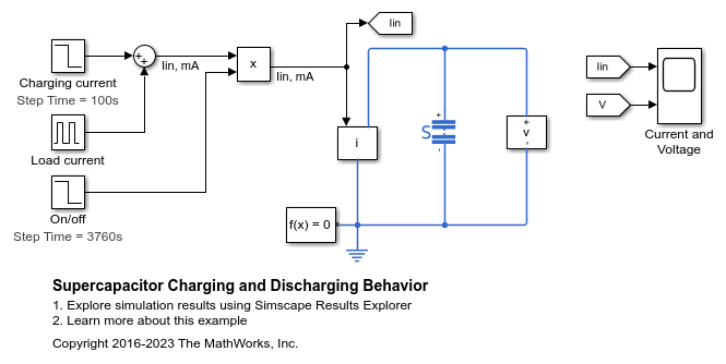
Supercapacitor Charging and Discharging Behavior
The voltage output by a Supercapacitor block as it is charged and then discharged. To charge the Supercapacitor, a current of 100 mA is input to the Supercapacitor for 100 seconds. The Supercapacitor is then rested for one minute. For the next hour, to discharge the Supercapacitor, a load of 50 mA is stepped on for one second in every 50 seconds. The Supercapacitor is then rested until the end of the simulation. The scope displays the Supercapacitor charging/discharging current and voltage.
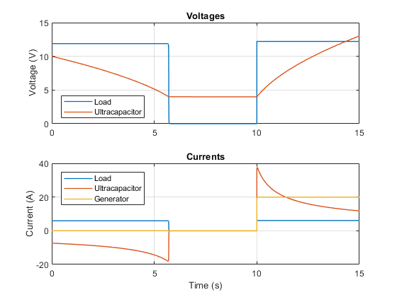
Ultracapacitor with Converter
Use a DC-DC converter to maintain a constant load voltage when drawing power from an ultracapacitor. The converter supplies power to the load and the capacitor voltage drops. The protection circuit disconnects the load when the capacitor voltage drops below a threshold value of 4V. At 10 seconds, the generator turns on, supplies power to the load and charges back the capacitor.
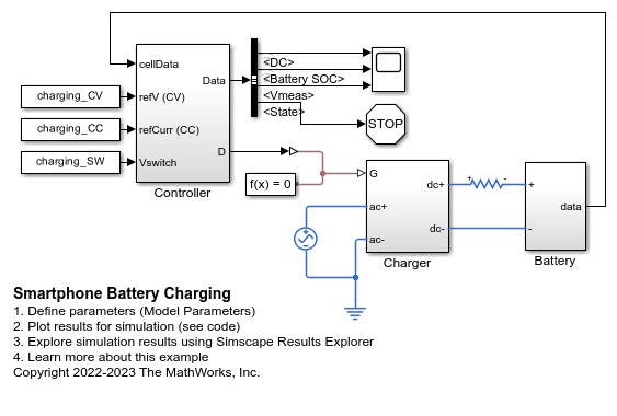
Smartphone Battery Charging
Set up a constant current (CC) and constant voltage (CV) charging on a typical battery in a smartphone. A constant current starts charging the battery. When the battery voltage reaches a specific value, the constant voltage charging process starts.
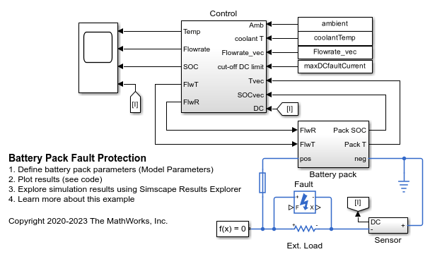
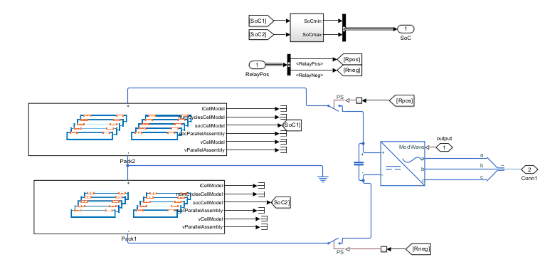
Battery Pack Fault Protection
Model fault and fault protection using a fuse in an automotive battery pack. The battery pack consists of several battery modules, which are combinations of cells in series and parallel. Each battery cell is modeled using the Battery (Table-Based) Simscape Electrical block. In this example, the initial temperature and the state of charge are the same for all cells. Four battery modules, three similar and one differing from the other three, are connected in series to simulate a battery pack. The results in this example assume an initial ambient temperature equal to 25 degree Celsius. The Control subsystem defines the logic used to determine the battery pack coolant flow rate. A fuse is placed inline to battery pack as a measure of fault protection.
利用电池储能系统进行调峰
此示例展示了如何对电池储能系统 (BESS) 控制器和电池管理系统 (BMS) 进行建模,并包含调峰所需的所有功能。调峰和 BESS 运行遵循 IEEE Std 1547-2018 和 IEEE 2030.2.1-2019 标准。