PMSM Parameterization from Measurements
This example shows how to identify PMSM motor parameters from experimental measurements.
Model
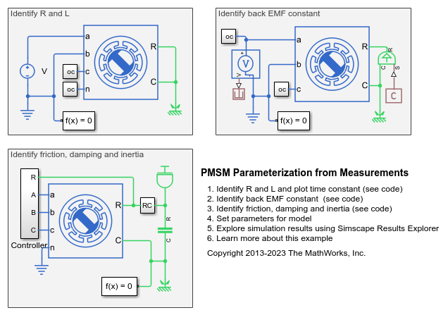
The parameter identification requires three separate tests that are represented here by three models as shown below. In this example we assume known values for the motor parameters and then show that we can reproduce them from the simulated identification tests.

Locked Rotor Test: Identify R and L
The first step is to lock the rotor and apply a voltage step to one of the stator windings. The resulting first-order time constant is defined by the stator resistance and inductance values, and the steady-state current by the stator resistance.

Fixed Speed No Load Test: Identify Back EMF Constant
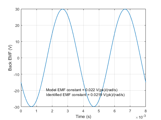
The second step is to spin the motor in a dynamometer with no electrical load. This permits estimation of the back EMF constant. Note that, when expressed in SI units, the back EMF constant is equal to the torque constant.

Controlled Motor Test: Identify Friction, Damping and Inertia
In this final step, the motor is spun using a motor controller and with no mechanical load. Mechanical torques due to friction and damping are measured by converting stator currents to torques using the already-identified torque constant.
The first plot below shows the mechanical torque required to maintain constant speed at four different speeds. The torque required at the lower speeds is primarily overcoming friction resistance, whereas at higher speeds viscous damping dominates. A straight line is fitted through the points, and the zero-speed intercept gives friction torque and the slope gives the viscous damping coefficient.
The second plot shows a speed run-down test. For this the demanded torque is set to zero, or the motor is unpowered. The gradient gives the deceleration from which the motor inertia can be determined given values for friction and damping torques.
