Phasor-Mode Simulation Using Simscape Components
You can run your model in phasor mode to speed up simulation. In Simscape™, phasor mode is known as frequency-time equation formulation. In general, this formulation leads to accurate simulation of AC models using larger time steps than the traditional time formulation.
Use frequency-time equation formulation to speed up your simulation when:
Your simulation contains periodic AC signals with a common fundamental frequency
You are interested in the slow-moving AC-related quantities, such as amplitude or phase, and the DC output signals
Set Up the Model
To measure the time required to run a simulation, open the model SMControl and create a model callback.
mdl = load_system('SMControl');
open_system(mdl);
set_param(mdl,'StartFcn','tic;');
set_param(mdl,'StopFcn','tsim=toc;');

Run a Time-Based Simulation
Double-click the Solver Configuration block and apply the following configuration:
Enable the local solver by checking the Use local solver check box
Set the
Sample timeparameter to1e-3Set the
Equation formulationparameter toTime
You can also run this code to configure the block.
blk = find_system(mdl,'MaskType','Solver Configuration');
set_param(blk,'UseLocalSolver','on');
set_param(blk,'LocalSolverSampleTime','1e-3');
set_param(blk,'EquationFormulation','NE_TIME_EF');
Simulate the model and save the run time and logging variable.
sim(get_param(mdl,'Name'));
tsim_time = round(tsim,2);
simlog_ee_sm_control_time = simlog_SMControl;
Run a Phasor-Mode Simulation
Double-click the Solver Configuration block and apply the following configuration:
Enable the local solver by checking the
Use local solvercheck boxSet the
Sample timeparameter to1e-2Set the
Equation formulationparameter toFrequency and time
You can also run this code to configure the block.
blk = find_system(mdl,'name','Solver Configuration');
set_param(blk,'UseLocalSolver','on');
set_param(blk,'LocalSolverSampleTime','1e-2');
set_param(blk,'EquationFormulation','NE_FREQUENCY_TIME_EF');
Simulate the model and save the run time and logging variable.
sim(get_param(mdl,'Name'));
tsim_phasor = round(tsim,2);
simlog_ee_sm_control_phasor = simlog_SMControl;
Compare DC Results
Plot the field voltage and rotor speed for both the time and frequency-time simulations. For each simulation mode, display markers at every 50 data points.
[hTime,hPhasor]=setup_figure(simlog_ee_sm_control_time,simlog_ee_sm_control_phasor,'dc');
legend([hTime,hPhasor],{['Time (t=',num2str(tsim_time),'s)'],['Phasor (t=',num2str(tsim_phasor),'s)']});

The phasor simulation reproduces near-identical results as the time-based simulation, despite using a time step that is 10 times larger. The measured simulation time is also shown for each of the simulation modes in the plot legend. This performance indicator is different on different machines, but the frequency-time simulation should be about two times faster than the time simulation. Note that the actual time required per step is higher in the frequency-time case, but the overall time is reduced.
Compare AC Results
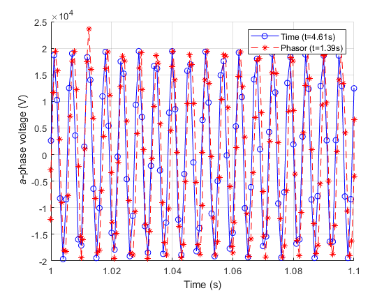
Plot the a-phase voltage of the synchronous machine over the time period 1s to 1.1s. Because of the larger time steps in the frequency-time formulation, the resolution of the AC quantity is too small to make out the sine wave. The points that are available are undersampled, but still accurate.
[hTime,hPhasor]=setup_figure(simlog_ee_sm_control_time,simlog_ee_sm_control_phasor,'ac');
legend([hTime,hPhasor],{['Time (t=',num2str(tsim_time),'s)'],['Phasor (t=',num2str(tsim_phasor),'s)']});

In general, use frequency-time formulation to speed up simulations where the outputs of interest are DC or slow-moving AC quantities. You can use periodic sensors to measure slow-moving properties of AC signals such as amplitude and phase in both time and frequency time formulations. For more information, see the PS Harmonic Estimator (Amplitude, Phase) block.
Sometimes there are small phase offsets between time- and frequency-time-generated AC signals. This difference is caused by the accumulated integration error of a slightly different signal frequency over time.