Model Rechargeable Battery System by Using a State Transition Table
State transition tables model finite state machine machines as tables, where the rows represent states and the columns represent transitions. For more information about finite state machines, see Design Finite State Machines in Stateflow.
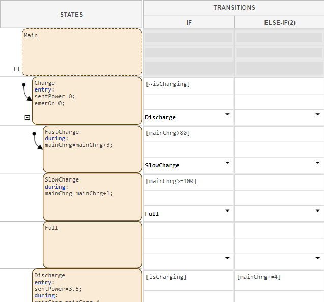
In this tutorial, you create a state transition table that models a rechargeable battery system. The system has two batteries that contain multiple operating modes and execute in parallel. The state transition table is a block in a Simulink® model, and receives data from and outputs data to other blocks in the model.
In this tutorial, you start with a basic state transition table and add new functionality.
Create State Transition Tables: Create a state transition table that executes code and shares data.
Log, Verify, and Debug State Transition Tables: Use debugging tools to understand how a table executes.
Create Parent and Child Operating Modes in State Transition Tables: Create a hierarchy of nested states.
Execute States in Parallel in State Transition Tables: Activate multiple states in the same time step.