Execute States in Parallel in State Transition Tables
You can simultaneously activate every state in the same level of hierarchy of a state transition table by using parallel decomposition. When a table or state that uses parallel decomposition becomes active, every direct child of the table or state also becomes active. The children, which are called parallel states, appear in the table with a dashed border.
In this step of the tutorial, you use parallel states to add a non-rechargeable emergency battery to the battery control system. If the main battery runs out of power, the backup battery maintains its essential functions.
Open Model
The sfGetStartedBatteryParallelTable model represents the control logic for a rechargeable battery system.
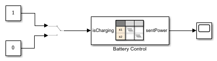
The State Transition Table block Battery Control contains the control logic for the system. To determine whether the battery charges or discharges, the table receives a Manual Switch block as an input.
To view the table, double-click the State Transition Table block. To see additional states, scroll up or down.
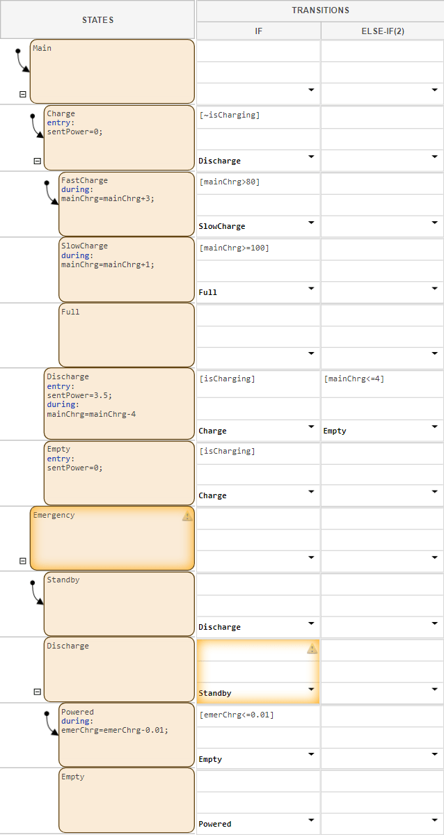
The table has two non-parallel states that represent the main and emergency batteries. Each battery has nested child states that represent operating modes for charging, discharging, running out of power, or standing by. Additionally, the batteries use these data:
isCharging: An input that determines whether the battery should charge or discharge.mainChrg: A local data that represents the charge level of the main battery as a percent of total charge.emerChrg: A local data that represents the charge level of the emergency battery as a percent of total charge.sentPower: An output that determines how many watts of power the battery system sends at any given time.
For details on the operation of the main battery, see the previous steps in the tutorial.
Enable Parallel Decomposition
Enable parallel execution for child states by right-clicking the parent component and selecting Decomposition > Parallel.
Because the Main and Emergency states do
not have a parent state, the table is the parent. To enable parallel
decomposition for the table, in the Modeling tab, select
Decomposition > Parallel (AND). The borders of
the two top-level states become dashed, which indicates they are parallel.
Note
To hide child states, on the left side of the parent state, click the
Hide child states button ![]() . To show hidden states, click the Show child states
button
. To show hidden states, click the Show child states
button ![]() .
.
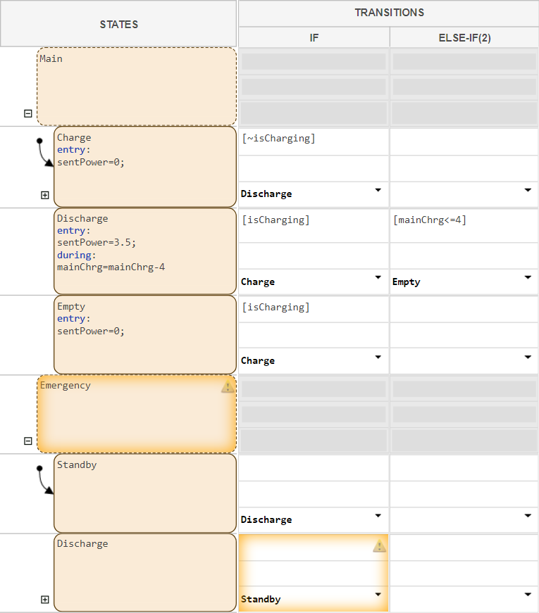
In state transition tables, states that use parallel decomposition do not
support transitions. In this table, the transition columns for parallel states
Main and Emergency are dimmed.
Coordinate Behavior Across Parallel States
When using parallel states, you can trigger behavior one state based on the activity of another. For example, in the battery system, the emergency battery switches on only if the main battery becomes empty. In state transition tables, you can coordinate behavior across parallel states by assigning a value to local data in one state, and creating a transition condition that uses the local data in another state.
Create local data that allows the main battery to activate or deactivate the emergency battery.
In the Symbols pane, click the Create Data button
 . Name the data
 emerOn.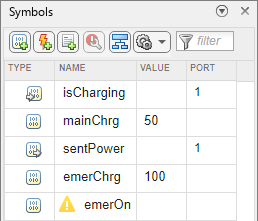
In the
Mainstate, in theChargechild state, in theentryaction, setemerOnto0. In theEmptychild state, in theentryaction, setemerOnto1.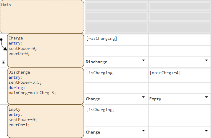
In
Emergency, in theStandbystate, add a transition that activates theDischargestate ifemerOnis true.In
Emergency, in theDischargestate, add a transition that activates theStandbystate ifemerOnis false.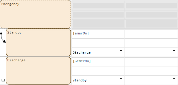
Simulate Model
Simulate the model.
Return to the top-level Simulink model. The Manual Switch block changes the operating mode of the main battery. When the value is
1, the battery charges. When the value is0, the battery discharges. Toggle the Manual Switch block so that it connects to the Constant block with a value of1.To simulate the model, in the Simulation tab, click Run.
Double-click the Manual Switch block. After a few seconds, double-click the Manual Switch block again. Repeat this process several times.
To stop the simulation, in the Simulation tab, click Stop.
To open the Simulation Data Inspector, in the Simulation tab, click Data Inspector.
To show the active child of each parent state, in the Inspect tab, select
Main:ActiveChildandEmergency:ActiveChild.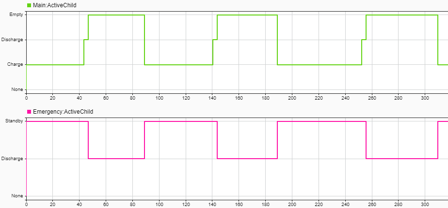
When the main battery is empty, the emergency battery discharges. When the
main battery leaves the Empty state and begins charging, the
emergency battery moves to standby.